Posted on

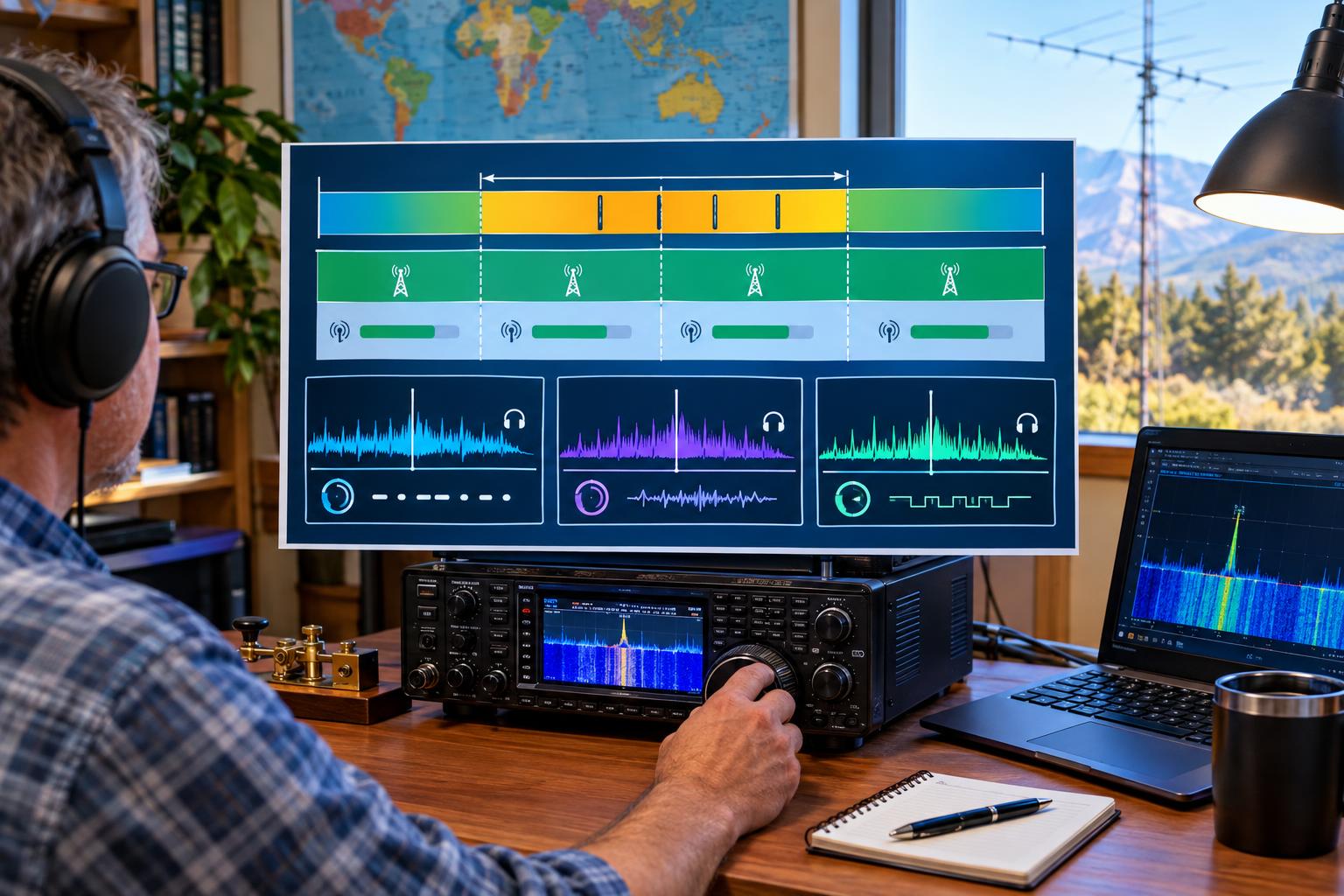
FT8 After a WSJT-X 3.x Upgrade: Audio Levels, CAT Control, Filters, and SuperFox Settings That Actually Matter

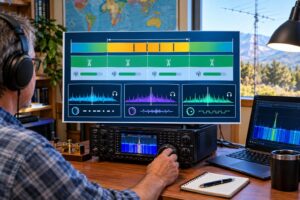
Why a WSJT-X 3.x Upgrade Can Break a Previously Good FT8 Station

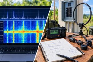
Upgrading WSJT-X is usually worthwhile, but it can expose weak spots in an FT8 station that were previously hidden: a renamed audio device, a changed CAT port, a different default behavior, or a radio menu setting that no longer matches the software. The official WSJT-X download page and release notes show active 3.x development, including the April 2026 3.0.0 feature set, June 2026 3.0.2 fixes, and later 3.2.0 release-candidate work. That pace is good for capability, but it also means operators should treat a major upgrade like a station checkout, not just a routine app launch.

This WSJT-X FT8 setup guide focuses on the settings that most often decide whether you decode reliably, transmit cleanly, and avoid chasing false problems. It is written for typical US HF operation, but licensing privileges, allocations, power limits, RF exposure requirements, and band plans vary by jurisdiction. Always follow your current regulator rules and the manufacturer instructions for your radio and interface.

Start With a Clean Baseline

Before changing menus at random, make a baseline. Confirm the installed version from within WSJT-X, read the current notes, and verify that your old configuration was imported as expected. If you are moving from a stable 2.x installation to a current 3.x build, keep a copy of your old configuration and log files before experimenting.

  • Confirm time synchronization: FT8 needs accurate computer time. Use a reliable time service and verify that the clock is within about a second of network time.
  • Confirm the correct mode: Select FT8 for ordinary contacts. Do not use Fox/Hound or SuperFox-related behavior unless the DX station specifically announces that operating style.
  • Confirm the band and frequency: Make sure the radio and WSJT-X agree. If the displayed band is wrong, logging, alerts, and transmit control may also be wrong.
  • Confirm your station details: Check call sign, grid square, IARU region if applicable, and reporting preferences.

Do not assume that because decodes appear, everything is correct. A station can decode well while transmitting with distorted audio, disabled split behavior, or an incorrect logging path.

CAT Control: Make the Radio and WSJT-X Agree First

CAT control is the foundation for an orderly WSJT-X FT8 setup. Without it, WSJT-X may not know the band, cannot reliably control frequency, and may fail to use split correctly. In the Radio settings, select the correct rig model or an appropriate Hamlib-compatible option, then choose the correct serial port, baud rate, data bits, stop bits, handshake, and PTT method for your radio.

After an upgrade, the most common CAT problem is not the software itself. It is that the operating system renamed the USB serial adapter or the radio now appears on a different port. Windows updates can also reassign COM numbers, and some radios expose more than one virtual port. If Test CAT fails, verify the port in the operating system device list before changing every WSJT-X setting.

Practical CAT Checklist

  • Test CAT before transmit: Use the built-in CAT test. The frequency display should follow the radio and the radio should follow WSJT-X band changes.
  • Choose one PTT path: Use CAT, RTS, DTR, or VOX intentionally. Avoid enabling multiple push-to-talk paths unless the radio manual requires it.
  • Use data mode when available: Many modern transceivers have USB-D, DATA-U, or similar modes that route audio through the USB interface and apply digital-mode settings.
  • Check frequency polling: If the display lags badly or jumps, reduce conflicts with other logging or control software.
  • Close competing programs: Only one program should normally control the same serial CAT port unless you use a proper rig-control server or virtual port arrangement.

If CAT works but PTT does not, separate the problem. First confirm CAT frequency control. Then test PTT. Then test audio. Combining all three at once makes troubleshooting much harder.

Audio Input: Decode Reliably Without Clipping

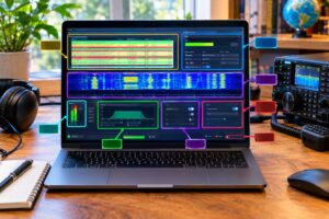
FT8 decoding depends on clean receive audio. In WSJT-X, the receive level indicator should sit in a healthy range without running into overload. The exact display behavior can vary by version and operating system, but the principle does not: avoid both a barely moving level and a constantly saturated one.

Set the radio for a reasonably wide digital receive passband, then adjust the computer recording level and radio output level so the waterfall shows signal texture without heavy clipping. If every strong station is a thick block, the sound path may be overdriven. If the waterfall is nearly empty while the radio S-meter is active, the wrong audio device may be selected or the level may be too low.

Receive Audio Steps

  • Select the radio USB audio device or external interface input, not the laptop microphone.
  • Turn off operating-system enhancements, noise suppression, automatic gain, and communications ducking where possible.
  • Use a stable sample rate expected by the software and device. Many digital-mode interfaces work well with 48 kHz settings, but follow your device documentation.
  • Adjust the radio audio output and computer recording gain together. Do not use maximum levels everywhere.
  • Watch the waterfall across several FT8 cycles before deciding the level is wrong.

A useful test is to tune to an active FT8 segment and observe both weak traces and strong local signals. You want weak signals visible and strong signals not flattened into audio mush.

Transmit Audio: Clean FT8 Beats Loud FT8

FT8 is a narrow, structured digital signal. It does not benefit from speech processing, compression, aggressive equalization, or ALC-driven audio. After a WSJT-X upgrade, verify transmit audio before calling CQ or answering DX. A station that is too hot may still complete contacts, but it can create unnecessary splatter, intermodulation products, and complaints.

The usual approach is simple: set the radio to its digital mode, turn off speech processor and transmit EQ effects unless the manufacturer specifically recommends otherwise, set RF power to a reasonable level, and use the WSJT-X power slider plus the operating-system playback level to keep ALC minimal or absent. Many operators aim for no visible ALC action on radios where that is the manufacturer recommendation for data modes. Some radios meter ALC differently, so the radio manual remains the authority.

Transmit Audio Checklist

  • Use the correct playback device: Select the radio or interface speaker output, not the computer speakers.
  • Disable processor features: Speech processing, compressor, noise gates, and voice equalizers are usually wrong for FT8.
  • Set power deliberately: FT8 has a high duty cycle. Use conservative power that your radio, tuner, feed line, and antenna system can sustain.
  • Watch ALC and current draw: Reduce audio drive if ALC rises unexpectedly or the transmitter sounds strained.
  • Check SWR and heat: Digital duty cycle stresses equipment more than casual SSB voice operation.

For example, if your transceiver is set to 50 watts but the ALC meter moves hard on every FT8 transmit cycle, reduce the audio drive rather than simply reducing RF power. The goal is not maximum meter movement. The goal is a clean RF envelope at the desired output.

Split Mode: Why Fake It and Rig Matter

WSJT-X can manage transmit audio placement in ways that help keep the generated tone in a clean part of the audio passband. Split operation is part of that strategy. Depending on the radio, WSJT-X may offer options such as using the rig split function or a software-managed method often called Fake It. The best choice depends on how well your radio supports CAT split and how cleanly it behaves with audio tones across the passband.

If your radio supports reliable CAT split, Rig may work well. If not, Fake It often provides practical frequency management by shifting the radio frequency while keeping the audio tone in a better range. The important point is not the name of the option; it is that your transmitted FT8 signal should be generated cleanly and land where WSJT-X says it will land.

  • Use the WSJT-X Tune function only into a proper load, antenna system, or safe station setup.
  • Confirm that changing TX audio frequency does not produce strange jumps or transmit outside the intended passband.
  • Do not disable split just because it seems simpler. Test it first, especially if you operate across the full FT8 waterfall.

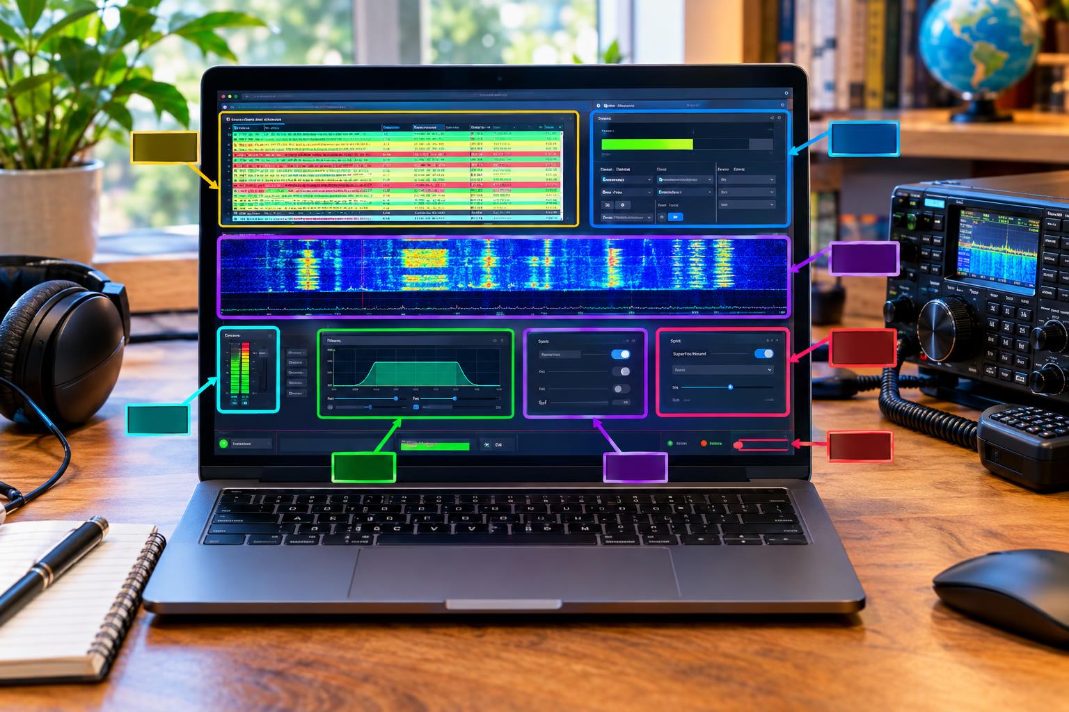
Filters and Passband: Do Not Decode Through a Keyhole

One common post-upgrade complaint is missing decodes. Sometimes the software is fine; the radio filter is too narrow. FT8 activity commonly occupies a few kilohertz of audio spectrum. If the transceiver is still using a narrow CW, RTTY, or custom data filter, WSJT-X will only see part of the activity.

For ordinary FT8, use a digital receive filter wide enough to cover the active audio range shown in the waterfall. Many operators use about a 3 kHz receive bandwidth when the radio and local interference conditions allow it. If you are fighting a strong nearby signal, narrowing the filter may help, but remember that anything outside the passband cannot be decoded.

Filter Settings That Matter

  • Receive bandwidth: Wide enough to cover the wanted FT8 waterfall, not accidentally set to a very narrow filter.
  • Transmit bandwidth: Compatible with the selected digital mode and tone range.
  • Notch filters: Useful against a carrier, but a deep notch can erase decodable FT8 signals.
  • Noise reduction: DSP noise reduction can sometimes make the waterfall look cleaner while making decodes worse. Compare on and off.
  • AGC: Use a setting that avoids pumping from strong signals. Exact recommendations vary by radio.

If decodes appear only below 1500 Hz on the waterfall, suspect a receive filter or audio routing issue. If you see signals but decode none, suspect time synchronization, wrong mode, or severe audio distortion.

Alerts, Colors, and Logging: Recover Your Operating Workflow

After the radio transmits and decodes properly, rebuild the operating workflow. Alerts and colors help you notice wanted grids, states, DXCC entities, call signs, or CQ messages. Logging confirms that completed QSOs are saved where you expect them. These features are easy to overlook during an upgrade because they do not stop FT8 from working, but they affect how useful the station feels.

  • Review color rules: Confirm that wanted DXCC, wanted grid, worked-before, and CQ highlighting still match your goals.
  • Check audio alerts: Make sure alerts are not muted by the operating system or routed to the wrong output.
  • Verify log location: Confirm that WSJT-X is writing to the expected ADIF log file.
  • Confirm external logging: If you use a separate logger, confirm UDP, TCP, file import, or companion app settings after the upgrade.
  • Test with one real QSO or a dummy-safe review: Do not wait until a rare station appears to discover that logging is broken.

Be careful with automated behavior. Alerts are aids, not substitutes for operator judgment. Confirm call signs, reports, and band information before logging or uploading.

SuperFox and Hound Behavior: Use It Only When Appropriate

SuperFox-related operation is intended for specific high-rate DXpedition-style scenarios, not normal everyday FT8 calling. The official SuperFox User Guide should be your primary reference because behavior, terminology, and authentication details can change with current releases. In practical station terms, the most important rule is simple: do not enable SuperFox or Hound-style settings unless the DX station instructions call for them.

For ordinary FT8, leave the station in normal FT8 behavior. For a published DXpedition using SuperFox, read the operator instructions before transmitting. Expect the software to manage certain transmit and receive behaviors differently than normal FT8. Do not manually fight the program by constantly moving your transmit audio, retuning the VFO, or changing modes mid-sequence unless the guide or DX station instructions tell you to do so.

SuperFox Readiness Checklist

  • Install a current WSJT-X build from the official source, not an unknown mirror.
  • Read the current SuperFox User Guide before the event.
  • Confirm your clock, CAT, split, and audio levels in normal FT8 first.
  • Use SuperFox/Hound behavior only for stations explicitly operating that way.
  • Follow the DX station instructions for calling frequency range, sequencing, and logging expectations.

If you cannot decode the SuperFox station, fix receive first. If you can decode but never receive a response, do not assume more power is the answer. Check that you are using the correct operating mode, transmit audio range, timing, and split behavior.

A Fast Troubleshooting Flow After an Upgrade

When FT8 stops working after a WSJT-X 3.x upgrade, troubleshoot in layers:

  • No waterfall: Wrong input device, muted radio audio, incorrect data mode, bad USB audio selection, or operating-system privacy/audio setting.
  • Waterfall but no decodes: Bad computer time, wrong mode, too much distortion, too-narrow filter, or audio level far outside the useful range.
  • Decodes but no transmit: PTT method wrong, CAT conflict, radio in receive-only state, wrong sound output, or transmit disabled in WSJT-X.
  • Transmits but no one answers: Overdriven audio, no split control, antenna/SWR issue, poor propagation, wrong band, or calling outside the expected audio range.
  • Logged contacts missing: ADIF path changed, external logger not listening, network permissions changed, or operator did not complete the log prompt.

Change one thing at a time. Write down the original setting before altering it. The fastest repair is often restoring the correct audio device or COM port, not reinstalling the program.

Key Takeaways

  • A WSJT-X 3.x upgrade deserves a full station checkout: CAT, audio input, audio output, split, filters, alerts, and logging.
  • Clean transmit audio matters more than loud audio. Avoid processor features and excessive ALC.
  • Wide enough receive filtering is essential for seeing the FT8 activity you expect to decode.
  • Split behavior helps keep transmit tones in a clean operating range; test Rig or Fake It with your radio.
  • SuperFox/Hound behavior is specialized. Use it only when the target station and official guide call for it.

FAQ

Should I reinstall WSJT-X if FT8 stops decoding after an upgrade?

Usually not as the first step. Check computer time, audio input device, receive level, radio filter width, and selected mode first. Many post-upgrade failures are configuration or device-selection problems.

How much power should I run on FT8?

Use the minimum power needed for the contact conditions while staying within your license privileges, equipment ratings, RF exposure limits, and good amateur practice. FT8 is high duty cycle, so heat and clean audio drive are important.

Is SuperFox the new normal FT8?

No. Treat SuperFox-related operation as a specialized DXpedition-style tool. For everyday contacts, use normal FT8 unless the station you are calling specifically announces another procedure.

Why did my logger stop receiving QSOs?

An upgrade can change paths, permissions, network behavior, or UDP settings. Confirm the WSJT-X log file location and any external logger connection settings before assuming the QSO data is lost.
Official Resources

Posted on

POTA Activation Workflow: How to Plan, Spot, Log, and Upload a Clean Parks on the Air Activation

What a Clean POTA Activation Means

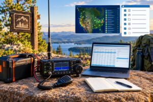
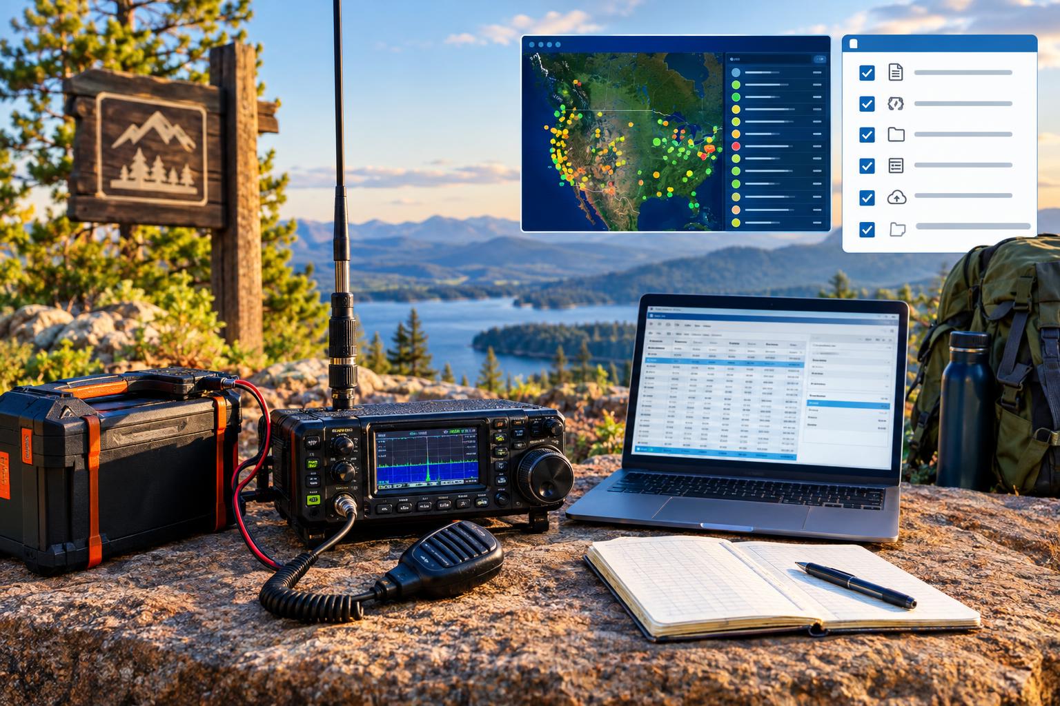
If you are learning how to activate POTA, the goal is not just to make contacts from a park. A clean activation is one where you are in the correct reference area, operate within your license privileges, make valid QSOs, log the right fields, and submit an ADIF file that awards credit without unnecessary corrections.

Parks on the Air is simple on the air, but the workflow matters. Most upload problems come from preventable issues: the wrong park reference, missing UTC times, incorrect call signs, a log exported without POTA fields, or confusion between ordinary hunter contacts and park-to-park contacts.

The official starting points are the live spots and schedules at POTA.app and the current POTA Activator Guide. Use them as the final authority because program details can change.

Step 1: Choose the Park Before You Choose the Gear

Begin with the park reference, not the radio. On POTA.app, search for parks near your route and confirm the exact reference, name, and boundaries. A valid activation depends on being inside the official reference area, not merely near a sign, visitor center, or similarly named public area.

For a first activation, choose a park with easy access, good operating space, and a simple antenna setup. A picnic table, open grassy area, or quiet parking-area edge can be better than a scenic spot with no way to deploy an antenna safely.

Park selection checklist

  • Reference confirmed: Write down the complete park reference, such as a United States K-prefix reference, exactly as shown in POTA.
  • Boundary checked: Use the POTA map and any park maps to confirm where you may legally and safely operate.
  • Access verified: Check hours, entrance rules, parking, trails, and seasonal closures from the park authority when needed.
  • Antenna-friendly location: Look for room to deploy a whip, vertical, end-fed wire, dipole, or VHF/UHF antenna without creating a trip hazard.
  • Backup plan: Identify a second operating spot inside the same reference in case your first choice is crowded or unsafe.

SOTA activations have a similar planning mindset, but different rules and geography. For Summits on the Air, the summit reference and activation zone matter. Do not assume POTA park-boundary logic applies to SOTA, or that SOTA logging requirements are identical.

Step 2: Build a Realistic Band, Mode, and Power Plan

A beginner-friendly POTA station can be simple: an HF transceiver, resonant or tunable antenna, feed line, battery, headphones or speaker, and logging device. Your plan should match the time of day, expected propagation, terrain, and your license privileges.

For many US operators, 20 meters is useful during daylight, 40 meters often supports regional contacts, and 17 or 15 meters may open well when conditions support higher bands. Those are practical tendencies, not guarantees. Always operate only where your license class permits and follow current FCC rules and applicable band plans.

Portable power planning

Estimate battery needs in watt-hours, not just amp-hours. The simple formula is:

Watt-hours = battery voltage x amp-hours

For example, a 12.8-volt 10 Ah LiFePO4 battery stores about 128 Wh before real-world losses and reserve. If your radio draws about 1 A on receive and much more on transmit, your operating time depends heavily on transmit duty cycle, RF power, digital mode use, screen brightness, and accessories. Digital modes and high-power calling can drain a small battery faster than casual SSB or CW.

  • Use fused power leads close to the battery.
  • Protect terminals from short circuits during transport.
  • Keep lithium batteries within the manufacturer’s temperature and charging limits.
  • Bring a lower-power option if your first band is slow and you need to stay longer.

Step 3: Schedule the Activation, Then Self-Spot When You Are Ready

POTA supports scheduled activations and live spots. A schedule tells hunters when and where you intend to operate; a spot tells them where you are actually calling. The distinction matters. Do not post a live spot until you are on frequency, listening, and ready to make QSOs.

The POTA Hunter Guide explains how hunters use spots. As an activator, think like a hunter: they need your call sign, park reference, frequency, mode, and enough confidence that you are still there.

Good spotting practice

  • Before the trip: Add a scheduled activation if your plan is reasonably firm. Include date, approximate UTC time, park, band or mode expectations, and your call sign.
  • At the park: Set up, check SWR, confirm your frequency is clear, and listen before transmitting.
  • Self-spot: Post your actual frequency and mode when you are calling CQ from inside the park.
  • Update when moving: If you QSY to a new band or mode, post a new spot or update as appropriate.
  • Do not chase your own bad data: If you mistyped the frequency, correct it quickly so hunters do not search the wrong place.

For CW and some digital operations, POTA documentation discusses assistance from spotting networks such as RBN-related workflows when your call and activation can be associated. Treat that as helpful support, not a substitute for knowing how to self-spot accurately.

Step 4: Make the First Ten Contacts Without Chaos

POTA activators commonly aim for at least 10 valid QSOs because that is the usual threshold for a credited activation under current POTA practice. Check the current activator documentation for any rule changes, special cases, or event-specific details.

A simple SSB call might be: CQ POTA, CQ Parks on the Air, this is W1ABC at park K-1234 calling CQ and listening. On CW, keep the exchange efficient. On digital modes, confirm that your software clock, call sign, grid, and station information are correct before calling.

Pileup control for new activators

  • Say the park reference often: Hunters need it for their logs, especially if they arrived from a spot late.
  • Use full call signs: Partial-call handling can help, but log the complete call before moving on.
  • Control the pace: If several stations answer, pick one call or suffix and ask others to stand by.
  • Confirm the essentials: Exchange signal reports as required by your operating style and make sure both stations know a contact occurred.
  • Take breaks: Portable operating is not a contest. Pause for battery checks, weather, visitors, and safety.

If the frequency becomes unusable due to QRM, another net, or poor conditions, announce that you are moving if possible, then QSY and update the spot. You are not obligated to fight a bad frequency.

Step 5: Handle Park-to-Park Contacts Carefully

Park-to-park contacts are one of the most enjoyable parts of POTA. They also demand better logging discipline. When another activator calls you, log the other station’s call sign and the other park reference. If that operator is at multiple references, capture each reference exactly as sent.

Your log should identify your activated park and the other operator’s park. In ADIF terms, POTA commonly uses fields such as MY_SIG and MY_SIG_INFO for your park program and reference, and SIG and SIG_INFO for the contacted station’s park information. Logging programs vary, so verify that your export includes the POTA data the current system expects.

Park-to-park logging example

  • Your call: W1ABC
  • Your park: K-1234
  • Other activator: N0XYZ
  • Other park: K-5678
  • Log note: Confirm that your ADIF export marks your reference as your activated park and the other reference as the contacted park.

If you are activating from an area that qualifies for more than one POTA reference, read the current POTA documentation before uploading. Multi-reference activations can be valid, but they are also where incorrect ADIF structure or reference handling can create avoidable credit problems.

Step 6: Log the Required Fields in UTC

Clean logging starts before the first CQ. Set your logging device to UTC or clearly understand how it records time. POTA uses electronic log submission, so consistent dates and times matter. A paper log is fine in the field, but it must be transcribed accurately before upload.

Minimum practical fields to capture

  • Call sign worked: Write or type the complete call sign.
  • QSO date: Use UTC date, especially near local evening when UTC may already be the next day.
  • Time: Record UTC time, normally the start time of the QSO.
  • Band or frequency: Band is commonly sufficient in many logs, but frequency can be useful.
  • Mode: Use the proper ADIF mode or submode supported by your logging program.
  • Your station call: Important if operating under a club call, portable call area, or with a different operator.
  • Your park reference: Ensure the activated POTA reference is in the proper POTA field or upload context.
  • Park-to-park reference: Capture the other activator’s POTA reference when applicable.

Common transcription errors include confusing zero and letter O, copying a slash incorrectly, entering local time as UTC, and exporting the wrong station profile. Before upload, scan the log for impossible bands, missing modes, duplicate lines, and call signs that look suspicious.

Step 7: Export ADIF and Check It Before Uploading

POTA uses ADIF log submission. ADIF is a standard amateur radio interchange format, but not every export is equally clean. Before uploading, open the ADIF file in a text editor or your logging software’s ADIF viewer and verify that the essential fields are present.

Pre-upload ADIF checklist

  • The file contains only QSOs for the activation you intend to submit, unless your logging method and POTA workflow clearly support the combined case.
  • Your call sign and operator call sign are correct.
  • Dates and times are in UTC and match the activation day.
  • Bands and modes are valid ADIF values.
  • Your POTA reference is correct.
  • Park-to-park references are included for applicable QSOs.
  • Duplicate or aborted contacts are removed unless they represent legitimate separate QSOs on another band or mode.

Upload through the official POTA process described in the current activator guide. Hunters generally do not need to submit your QSO for you to receive activator credit; the activator’s uploaded log is the key record. However, hunters still benefit when your log is accurate because it drives their hunter and park-to-park credit too.

Safety and Regulatory Caveats

Portable radio is enjoyable, but it is still field work with RF, batteries, wires, weather, and public spaces. Follow FCC rules, your license privileges, RF exposure requirements, and local park regulations. Do not attach antennas to prohibited structures, block trails, create trip hazards, or leave wire in trees.

  • Keep antennas away from power lines, roads, and crowded walkways.
  • Use visible cord, cones, or low-profile routing where people might walk.
  • Lower antennas before thunderstorms or high winds arrive.
  • Carry water, sun protection, and weather-appropriate clothing.
  • Respect quiet areas, wildlife, and other park users.

Also remember that technical capability is not the same as legal permission. Your radio may tune somewhere you are not authorized to transmit. Your antenna may handle power that creates RF exposure concerns at close range. When in doubt, reduce power, increase distance, and verify the rule.

Quick Activation Workflow

  • At home: Confirm the park reference, boundaries, access, license privileges, likely bands, antenna plan, battery capacity, and logging method.
  • Before leaving: Charge batteries, pack fuses and adapters, update software if needed, print or save the park reference, and create a scheduled activation if appropriate.
  • On site: Confirm you are inside the reference, deploy safely, check SWR, listen first, choose a clear frequency, and self-spot.
  • While operating: Call CQ, give the park reference regularly, manage pileups calmly, log every QSO in UTC, and capture park-to-park references.
  • Before packing: Count contacts, check for obvious log errors, save a backup, and announce QRT if practical.
  • At home: Export ADIF, inspect required fields, correct mistakes from notes or recordings if you made them legally and appropriately, then upload through POTA.

FAQ

Can I spot myself for POTA?

Yes. POTA documentation supports practical self-spotting. It helps hunters find you and is especially useful for new activators, QRP stations, and band changes.

Do I need exactly 10 contacts?

Current POTA practice commonly uses 10 valid QSOs as the activation threshold. More contacts are fine, and a short log can still be worth keeping, but check the current official guide for the latest rule language.

Are repeater contacts valid?

Do not assume terrestrial repeater contacts qualify. POTA rules and activation styles can distinguish among simplex, satellites, repeaters, and other methods. Check the current POTA activation styles documentation before relying on a method.

What is the most common upload mistake?

The most common category is mismatched data: wrong UTC date, wrong park reference, missing POTA ADIF fields, or a log exported from the wrong station profile. A five-minute ADIF review prevents many problems.

Key Takeaways

  • Plan from the park reference outward: boundary, access, antenna, power, band, and logging.
  • Use scheduled activations for intentions and spots for real-time operating.
  • Self-spot only when you are actually ready to work stations.
  • Log in UTC and capture complete call signs, band, mode, and POTA references.
  • Park-to-park contacts need both your reference and the other activator’s reference recorded correctly.
  • Inspect your ADIF before upload instead of discovering errors after credit is missing.
Posted on

Your First Amateur Satellite Contact in 2026: How to Pick an Active FM Bird, Program Doppler, and Avoid the Common Beginner Mistakes

Start with the right goal: one clean FM satellite QSO

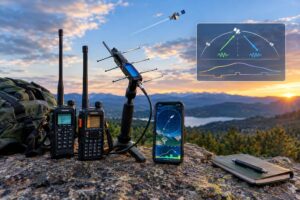
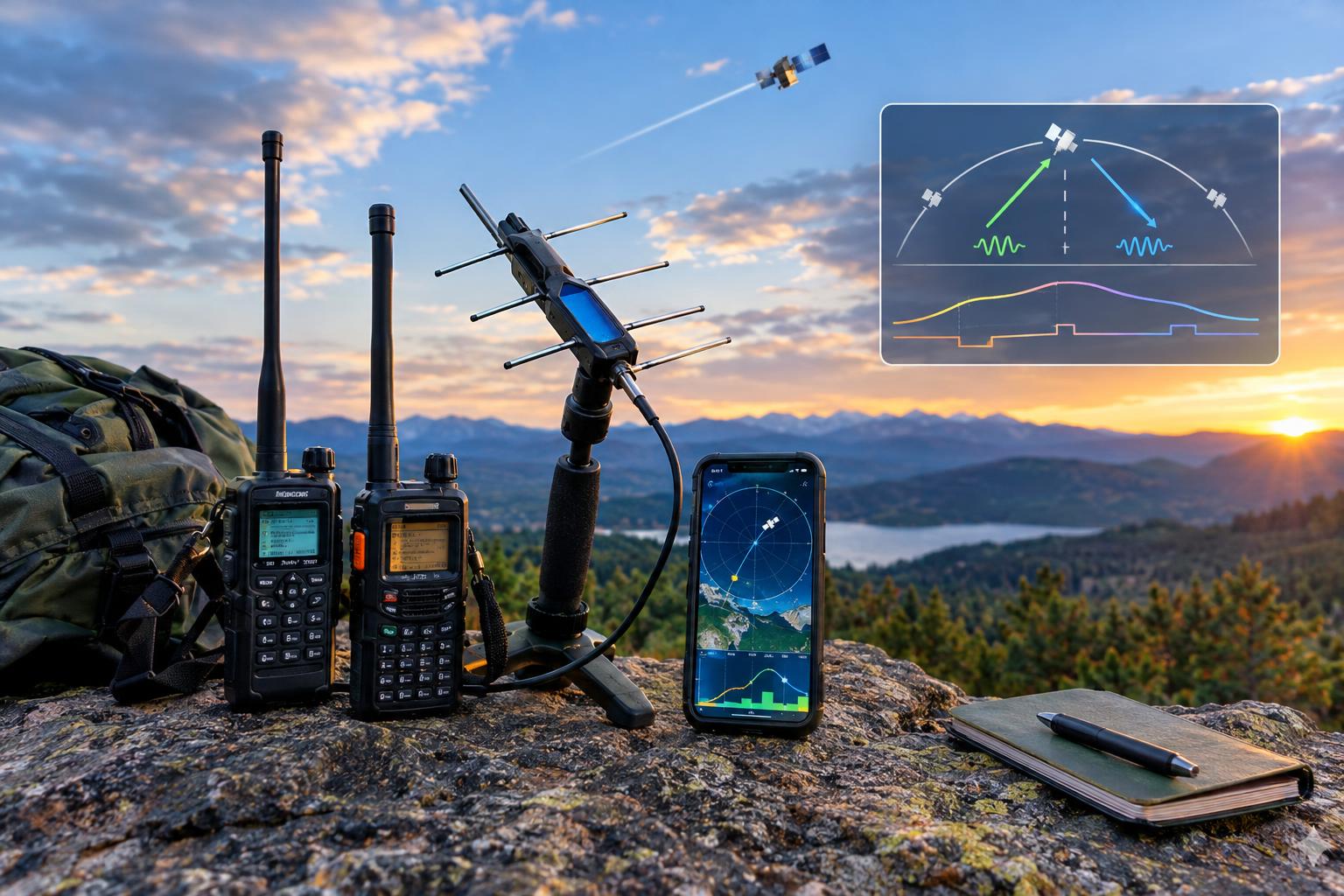
If you are learning how to work amateur radio satellites, your first goal should not be a rare grid, a long ragchew, or a perfect recording. Aim for one brief, accurate FM contact through an active satellite using modest gear: a dual-band handheld or mobile radio, a small directional antenna, current satellite status information, and a prepared logging method.

FM satellites are often described as “repeaters in space,” but they are not as forgiving as a local repeater. The pass may last only 8 to 14 minutes, Doppler shift changes the apparent frequency, the footprint may cover thousands of miles, and many stations may be trying to use one shared channel. Preparation matters more than transmit power.

The key is to verify that the satellite is actually usable today, choose a pass with favorable elevation, program uplink and downlink memories before you go outside, and keep your exchange short. The process below is written for U.S. operators, but the technical workflow applies broadly. Always confirm your license privileges, frequency allocations, power limits, and local regulations for your jurisdiction.

Step 1: Verify what is active before you plan the pass

Do not assume a satellite listed in an old chart, radio memory file, or video tutorial is currently operational. Amateur satellites change modes, go silent, enter experimental schedules, or become temporarily unavailable. In 2026, the practical starting point is still AMSAT’s current satellite information.

  • Check the AMSAT Live OSCAR Satellite Status Page for FM satellites. AMSAT’s live FM satellite list was updated October 31, 2026, and is intended to help operators see which FM birds are being reported active.
  • Check the broader AMSAT satellite status pages for recent user reports. Look for multiple recent observations, not a single stale report.
  • For International Space Station amateur-radio modes, check authoritative ARISS information such as the ARISS APRS page before planning for APRS or packet operation.

A useful status report does not merely say “heard it once.” For an FM voice QSO, you want evidence that the transponder or repeater mode is on, that stations are getting through, and that any required access tone or mode note is current. If reports are mixed, pick another pass or another satellite. Your first attempt is not the time to troubleshoot an uncertain spacecraft schedule.

Step 2: Pick a pass that helps you succeed

After selecting a currently active FM satellite, use your preferred satellite tracking app or desktop program to find passes for your exact location. Enter your latitude, longitude, and time zone accurately. A difference of several miles is usually tolerable for casual operating, but a wrong location or clock setting can make the satellite appear in the wrong part of the sky.

For a first FM voice contact, choose a pass with these traits:

  • Maximum elevation of at least 25 to 30 degrees. Higher is often easier because the path is shorter and local obstructions matter less.
  • A clear horizon path. A lower pass over open ground can beat a high pass blocked by buildings, trees, or a hill.
  • Reasonable timing. Avoid your very first try during a widely announced event, weekend pileup, or pass covering a dense operator area if you can.
  • Comfortable setup time. Be outside, radio checked, recorder running, and antenna oriented before acquisition of signal.

The terms AOS, TCA, and LOS are worth learning. AOS is acquisition of signal, when the satellite rises above your local horizon. TCA is time of closest approach, often near the highest point of the pass. LOS is loss of signal. Most beginner mistakes happen because the operator starts programming, logging, or aiming after AOS instead of before it.

Step 3: Understand the FM satellite signal path

An FM satellite normally listens on one band and retransmits on another. Many popular FM satellites use a VHF/UHF crossband arrangement, but the exact uplink, downlink, mode, and access tone must be confirmed from current sources. Do not blindly copy frequencies from an old memory file.

In satellite terminology, your uplink is the frequency you transmit to the spacecraft. The downlink is what you receive from the spacecraft. A CTCSS tone may be required on the uplink to access the FM repeater. Some satellites also have mode schedules, power-management behavior, or special notes from the control operator community.

Full-duplex operation, where you can hear the downlink while transmitting, is strongly recommended. It lets you know whether you are actually getting into the satellite and whether you are doubling with another station. Many handheld radios are not true full duplex across VHF/UHF. If yours is not, you can still learn reception and timing, but making courteous contacts is harder because you cannot monitor your own downlink while transmitting.

Step 4: Program Doppler memories before the pass

Doppler shift is the apparent frequency change caused by the satellite’s high relative motion. It is most noticeable on UHF, but it can affect both uplink and downlink. As a simple rule for FM satellite work: program several memory channels that step through the pass rather than trying to spin a VFO under pressure.

Many operators create five memories: beginning of pass, early-middle, center, late-middle, and end of pass. The exact values depend on the satellite’s published uplink and downlink and on whether the UHF side is uplink or downlink. Your tracking software may provide Doppler-corrected frequencies, or you can use a known satellite memory plan from a current, reputable source and verify it against AMSAT notes.

A typical memory set includes:

  • Receive frequency adjusted across the pass. If the downlink is on UHF, the receive correction can be several kilohertz from AOS to LOS.
  • Transmit frequency adjusted if needed. If the uplink is on UHF, stepping the transmit frequency helps the satellite hear you near the correct channel center.
  • Correct tone on transmit. Program the required CTCSS tone only where the current satellite information calls for it.
  • Wide FM or narrow FM as appropriate. Use the mode recommended for that satellite and your radio’s capabilities.
  • Clear labels. Name memories in pass order so you are not decoding cryptic channel names in the dark or cold.

For FM satellites, you usually do not need laboratory precision. You need to be close enough that the receiver captures your signal cleanly without splattering or fighting the passband. If the downlink sounds distorted or weak when the antenna is aimed well, step to the next Doppler memory and listen again.

Step 5: Assemble a modest first station

A common first setup is a dual-band HT, a handheld directional antenna, headphones or an earbud, and a phone or recorder to capture the pass. A small directional antenna helps far more than excessive transmit power. Many successful FM satellite QSOs are made with handheld equipment, but the operator’s preparation and antenna handling are what make it work.

Before the pass, check:

  • Battery charge. Cold weather can reduce battery performance. Start with a known-good battery.
  • Coax and connectors. Handheld antennas get moved constantly. A loose adapter can ruin an otherwise good pass.
  • RF power setting. Use the minimum power that reliably gets through. More power does not create more channels on a crowded FM satellite.
  • Recording method. Recording your received audio helps you log call signs and grid squares accurately after the pass.
  • Paper backup. A small notepad survives sun glare, dead phone batteries, and frozen fingers.

Safety matters. Do not point a transmitting antenna near someone’s face or body at close range, especially with higher-power mobile gear. Follow RF exposure requirements, maintain awareness of your surroundings, and avoid operating while walking near traffic, cliffs, rooftops, or wet electrical hazards. If you use a mast or larger antenna, consider overhead power lines, wind, lightning risk, and mechanical stability.

Step 6: Listen first, then transmit briefly

At AOS, point the antenna toward the predicted direction and listen. Rotate the antenna slowly for best signal; handheld satellite antennas often need changes in azimuth, elevation, and polarization. If the signal fades, do not assume the satellite is gone. Try rotating the antenna 90 degrees, adjusting elevation, or stepping the Doppler memory.

When you can hear the downlink and there is a gap, make a short call. A standard first call might be:

“W1ABC, FN42.”

That is enough. On a crowded FM satellite, long CQ calls waste time. Many satellite operators simply transmit their call sign and grid square. If another station answers, exchange call signs and grid squares clearly:

“N5XYZ, W1ABC, roger, FN42.”

If you are unsure you copied the call, ask once, briefly. If you still cannot confirm it, let the pass move on. Do not keep calling over active contacts. The satellite channel belongs to everyone in the footprint.

Step 7: Log the contact correctly

Most FM satellite contacts exchange call sign and Maidenhead grid square. In the United States, a grid such as FN42 or EM13 is commonly used for a basic contact. More precise six-character grids may be used for location detail, but the four-character grid is the usual quick exchange on busy passes.

Your log should include:

  • Date and time in UTC
  • Satellite name
  • Mode, such as FM voice or packet/APRS if applicable
  • Other station’s call sign
  • Sent and received grid squares
  • Your own operating location and grid
  • Any uncertainty, such as partial call copy or questionable grid

Do not log a contact you did not complete. Hearing a station is not a QSO. Transmitting your call without hearing confirmation is not a QSO. If you recorded the pass, replay it soon afterward while the details are fresh.

APRS and packet: related, but not the same as FM voice

APRS and packet through satellites or the ISS can be excellent operating goals, but they require a different setup and operating rhythm. Instead of voice exchange, you may use a packet TNC, software modem, radio interface, and the proper path settings for the current spacecraft or ISS mode. The ISS amateur-radio equipment is especially schedule-dependent, so confirm current ARISS information before assuming APRS is available.

For a first satellite experience, many operators benefit from this sequence: first learn to hear FM voice downlinks, then make a short voice QSO, then explore packet and APRS once antenna pointing, pass timing, and Doppler awareness feel natural.

Common beginner mistakes to avoid

  • Using outdated satellite data. Always check current AMSAT and ARISS information before heading outside.
  • Calling before hearing the downlink. If you cannot hear the satellite, you probably cannot operate courteously through it.
  • Ignoring Doppler. One fixed memory may work poorly, especially when UHF is involved.
  • Overpowering the channel. Excess power increases interference and does not improve shared-channel etiquette.
  • Talking too long. Short pass, short exchange. Save explanations for terrestrial repeaters.
  • Forgetting polarization. Rotate the handheld antenna when signals fade.
  • Logging from memory hours later. Record or write immediately, then verify after the pass.
  • Operating from a bad location. Buildings, trees, and local noise can make a workable pass seem impossible.

Quick first-pass checklist

  • Confirm the satellite is active on AMSAT’s live FM and status pages.
  • Confirm current uplink, downlink, tone, and mode notes.
  • Select a pass with good elevation and a clear view.
  • Program Doppler memories in pass order.
  • Charge batteries and check antenna connections.
  • Start recording before AOS.
  • Listen first; transmit only when you hear the downlink and a clear opening.
  • Exchange call sign and grid square briefly.
  • Log in UTC with satellite name, mode, and grids.

FAQs

Can I work an FM satellite with only an HT?

Sometimes, yes, especially with a suitable handheld directional antenna and a good pass. A stock rubber duck antenna is usually frustrating because satellite signals are weak, moving, and polarization changes during the pass.

Do I need computer control for Doppler?

No. Computer-controlled tuning is convenient, but many first FM contacts are made with preprogrammed Doppler memories. The important point is to plan the frequency steps before the pass.

Should I call CQ on an FM satellite?

Keep it short. Many satellite operators simply give their call sign and grid. Long CQ calls consume limited pass time and can block other stations.

What if I only hear one side of contacts?

That can happen because you hear the satellite downlink, not every station’s uplink directly. It may also indicate antenna aiming, Doppler, or local obstruction issues. Keep listening and adjust the antenna before transmitting.

Key takeaways

  • Successful satellite operating starts with current status checks, not old frequency lists.
  • FM satellites are shared, fast-moving repeaters with very short operating windows.
  • Program Doppler memories, required tones, and mode settings before the pass.
  • Listen first, use brief exchanges, and log grid squares accurately.
  • Good etiquette is technical skill: it lets more operators complete valid QSOs during the same pass.

Your first amateur satellite contact does not require a large station. It requires current information, a workable pass, disciplined operating, and respect for the shared channel. Prepare before AOS, keep the exchange simple, and each pass will teach you something useful for the next one.

Posted on

60 Meters in 2026: How U.S. Hams Should Operate the New 5351.5–5366.5 kHz Segment Without Breaking the Rules

What Changed on 60 Meters in 2026?

The 60 meter ham radio band 2026 changes give U.S. amateur operators something they have wanted for years: continuous secondary amateur access from 5351.5 to 5366.5 kHz. The FCC rule changes took effect February 13, 2026, and they sit alongside four retained discrete 60-meter channels outside that new segment.

The most important practical point is this: 60 meters is still not a normal HF band like 40 or 20 meters. It is shared spectrum, amateur stations are secondary, and the power and frequency rules require more care than simply spinning the VFO and calling CQ. The new segment adds flexibility for CW, digital, weak-signal work, emergency practice, and voice, but every signal must stay inside the applicable limits.

For official details, check the current ARRL 60 Meter FAQ, the ARRL 60-meter channel allocation page, the FCC Report and Order at FCC-25-60A1, and the Federal Register rule publication at 90 FR 2026-00587.

Who May Use 60 Meters?

Under U.S. amateur rules, 60-meter privileges are for General, Advanced, and Amateur Extra class licensees. Technician and Novice licensees do not receive these HF privileges simply because the new segment exists.

U.S. amateur stations operate on 60 meters on a secondary basis. That means you must not cause harmful interference to primary users, including federal users, and you must accept interference from them. If you hear traffic that appears to be non-amateur or official, do not argue, tune up, call over it, or try to “hold” a frequency. Move away.

The New Continuous Segment: 5351.5–5366.5 kHz

The new amateur segment is 15 kHz wide, from 5351.5 kHz to 5366.5 kHz. Unlike the older channelized structure, this is continuous spectrum. You may tune within it, but your entire occupied signal must remain inside the segment.

That last sentence is the trap. Your radio display is not always the same thing as the actual RF energy your station is transmitting. With USB voice and many sound-card digital modes, the transmitted RF appears above the displayed suppressed-carrier frequency. With CW, many radios display the actual carrier frequency, but settings vary. With digital modes, the audio offset in your software matters.

Practical USB Voice Tuning

For upper sideband voice, your audio energy is above the dial frequency. If your transmitted audio occupies roughly 300 to 2700 Hz, a dial setting too close to the top edge can put part of your signal outside the band.

A conservative approach is to keep ordinary USB voice dial frequencies no higher than about 5363.7 kHz if using a 2.8 kHz transmit bandwidth, and to leave additional guard room near both edges. Narrowing your transmit audio bandwidth helps, but do not rely on optimistic menu settings unless you understand your rig’s transmit filtering.

Practical Digital Tuning

For audio-derived digital modes on USB, the RF frequency equals:

RF frequency = radio dial frequency + audio offset

Example: if your radio dial is 5357.0 kHz and your digital software transmits at a 1500 Hz audio offset, the RF energy is centered around 5358.5 kHz. That is inside the new segment. This example is not a universal calling frequency recommendation; it simply shows how the math works.

Before transmitting FT8, JS8, Olivia, PSK, packet, VARA HF, or any other mode, confirm both the low and high edges of the occupied signal. A narrow mode is easier to place safely. Wider data modes demand more guard space and more attention to the 2.8 kHz emission bandwidth limitation commonly associated with 60-meter operation.

Practical CW Tuning

For CW in the continuous segment, make sure the actual transmitted carrier is within 5351.5–5366.5 kHz. Most modern transceivers display the CW carrier frequency, but operators should verify how their radio behaves in CW, CW-R, split, and transverter-style configurations. When in doubt, leave margin from the band edges.

The Four Retained Channels Outside the Segment

The 2026 rules did not simply replace all old 60-meter operation with one continuous segment. Four discrete channels remain outside the new 5351.5–5366.5 kHz segment. The commonly referenced channel center frequencies are:

  • 5332.0 kHz center frequency; typical USB dial: 5330.5 kHz
  • 5348.0 kHz center frequency; typical USB dial: 5346.5 kHz
  • 5373.0 kHz center frequency; typical USB dial: 5371.5 kHz
  • 5405.0 kHz center frequency; typical USB dial: 5403.5 kHz

The old 5358.5 kHz channel is the source of much confusion because it falls inside the new continuous segment. Treat operation there as operation within the new segment, not as a separate high-power legacy channel. Check the current ARRL and FCC references before relying on any memorized pre-2026 channel list.

Power Limits: Radio Output Is Not the Same as ERP or EIRP

Power is where many operators can accidentally break the rules. Your transceiver’s power control shows transmitter output power, not the radiated power limit used in the rules.

The new 5351.5–5366.5 kHz segment is associated with a 15-watt EIRP limit. EIRP means equivalent isotropically radiated power, referenced to an ideal isotropic radiator. By contrast, older U.S. 60-meter channel rules have commonly used ERP, or effective radiated power, referenced to a half-wave dipole.

The conversion matters because a half-wave dipole has about 2.15 dB gain over an isotropic radiator in its favored direction. As a result, 15 watts EIRP is about 9.1 watts ERP. This does not mean your radio must always be set to 9 watts. It means your final radiated-power calculation must account for antenna gain and feed-line loss.

Simple EIRP Calculation

Use this practical formula:

EIRP in watts = transmitter power × 10^((antenna gain in dBi − feed-line loss in dB) / 10)

Example: suppose your transmitter is set to 10 watts, your antenna is a half-wave dipole with about 2.15 dBi gain, and your feed line loss is 1 dB. The net gain is 1.15 dB. Your EIRP is about 10 × 10^(1.15/10), or roughly 13 watts EIRP. That is under 15 watts EIRP.

If the same dipole had nearly no feed-line loss, 10 watts transmitter output would be about 16.4 watts EIRP, which is above 15 watts EIRP. A conservative operator using a dipole in the new segment may choose a transmitter setting around 5 to 8 watts unless a more careful station calculation supports a higher setting.

Do not assume low SWR makes you legal. SWR tells you about impedance matching, not radiated power compliance.

Mode Setup Without Splattering Outside the Segment

Digital and Weak-Signal Modes

Digital modes are attractive on 60 meters because the 15-watt EIRP limit rewards efficiency. Use clean audio drive, keep ALC action minimal or absent for sound-card modes, disable speech processing, and avoid overdriving the radio’s USB input. A narrow, clean 5-watt digital signal is far more useful than a distorted one at the legal edge.

For weak-signal operation, set your waterfall range so you can see where your signal sits relative to the segment edges. If the software shows audio tones from 200 to 2800 Hz, remember that those tones are added to the radio dial frequency in USB. Keep both edges inside the allowed spectrum.

CW

CW is well suited to the new segment because it is narrow and efficient. Use reasonable keying speed, clean key shaping if your rig offers it, and avoid tuning right on the band edges. If you use an external keyer, amplifier, or QRP transmitter, verify that the displayed or selected frequency corresponds to the transmitted RF carrier.

Voice

Use USB, keep transmit audio bandwidth appropriate, and avoid excessive compression. On 60 meters, loudness is not the goal; a clean, intelligible signal is. If your radio has transmit equalization, avoid heavy bass that consumes bandwidth without improving readability.

Propagation: Why 60 Meters Is Useful

60 meters sits between 80 and 40 meters, which makes it valuable for regional communication. It can support NVIS-style paths of a few hundred miles when conditions cooperate, especially with horizontal antennas at moderate heights. It may also provide longer paths at night or around gray-line periods, but it is not magic and it is not always open.

Space weather matters. High solar activity can improve higher HF bands while D-layer absorption, geomagnetic storms, and nighttime ionospheric changes affect 5 MHz paths differently. For emergency and off-grid planning, do not treat 60 meters as a guaranteed link. Test multiple bands, maintain alternate modes, and keep realistic schedules with stations you are authorized to contact.

Emergency and Off-Grid Operating Considerations

The 5 MHz region is useful for emergency communications because it can bridge the gap between local VHF/UHF coverage and longer HF paths. However, amateur use remains secondary, and emergency intent does not erase the rules. Use the minimum power necessary, identify properly, log important tests, and avoid interfering with non-amateur users.

For field stations, a simple 60-meter dipole, inverted-V, or end-fed antenna can work well, but power calculations still apply. Battery voltage changes, tuner losses, feed-line type, and antenna placement all affect real-world performance. Also consider RF exposure compliance, safe generator placement, grounding and bonding, trip hazards, weather exposure, and lightning risk. No portable contact is worth an unsafe installation.

Quick Operating Checklist for 2026

  • Confirm you hold General, Advanced, or Amateur Extra privileges.
  • Use 5351.5–5366.5 kHz only with the entire signal inside the segment.
  • Remember that the old 5358.5 kHz channel is now within the continuous segment.
  • Use the four retained channels only as channels, not as open mini-bands.
  • Calculate EIRP or ERP as applicable; do not rely only on radio output power.
  • For digital modes, add audio offset to dial frequency to find RF frequency.
  • For USB voice, leave enough room below 5366.5 kHz for your full audio bandwidth.
  • Operate secondary: move if you encounter primary-user activity.
  • Keep signals clean, narrow, and no stronger than needed.
  • Recheck FCC and ARRL guidance because operating details can change.

FAQs

Can I use my old 60-meter memories?

Maybe, but review every memory. Old channel memories may still be useful for retained channels, but the former 5358.5 kHz channel should be understood in light of the new continuous segment and its power limit.

Is 15 watts EIRP the same as setting my radio to 15 watts?

No. EIRP includes antenna gain and feed-line loss. A dipole with little feed-line loss can exceed 15 watts EIRP with a 10-watt transmitter setting. Calculate conservatively.

Can I run FT8 or JS8 on 60 meters?

Digital operation can fit the new segment when the mode, bandwidth, dial frequency, audio offset, and power all comply with the rules. The operator is responsible for keeping the full signal inside the authorized spectrum.

Is 60 meters good for emergency communications?

It can be very useful for regional HF, especially when 80 meters is too low and 40 meters is too high for the desired path. But propagation varies, amateur use is secondary, and emergency planning should include alternate bands and modes.

Key Takeaways

The 2026 60-meter changes give U.S. hams more flexibility, especially for narrow digital modes, CW, weak-signal work, and regional emergency practice. The tradeoff is responsibility: know whether you are in the continuous segment or on a retained channel, calculate radiated power correctly, and keep your entire signal inside the authorized limits. When in doubt, reduce power, narrow your signal, leave more guard space, and check the current FCC and ARRL references before transmitting.

Posted on — Leave a comment

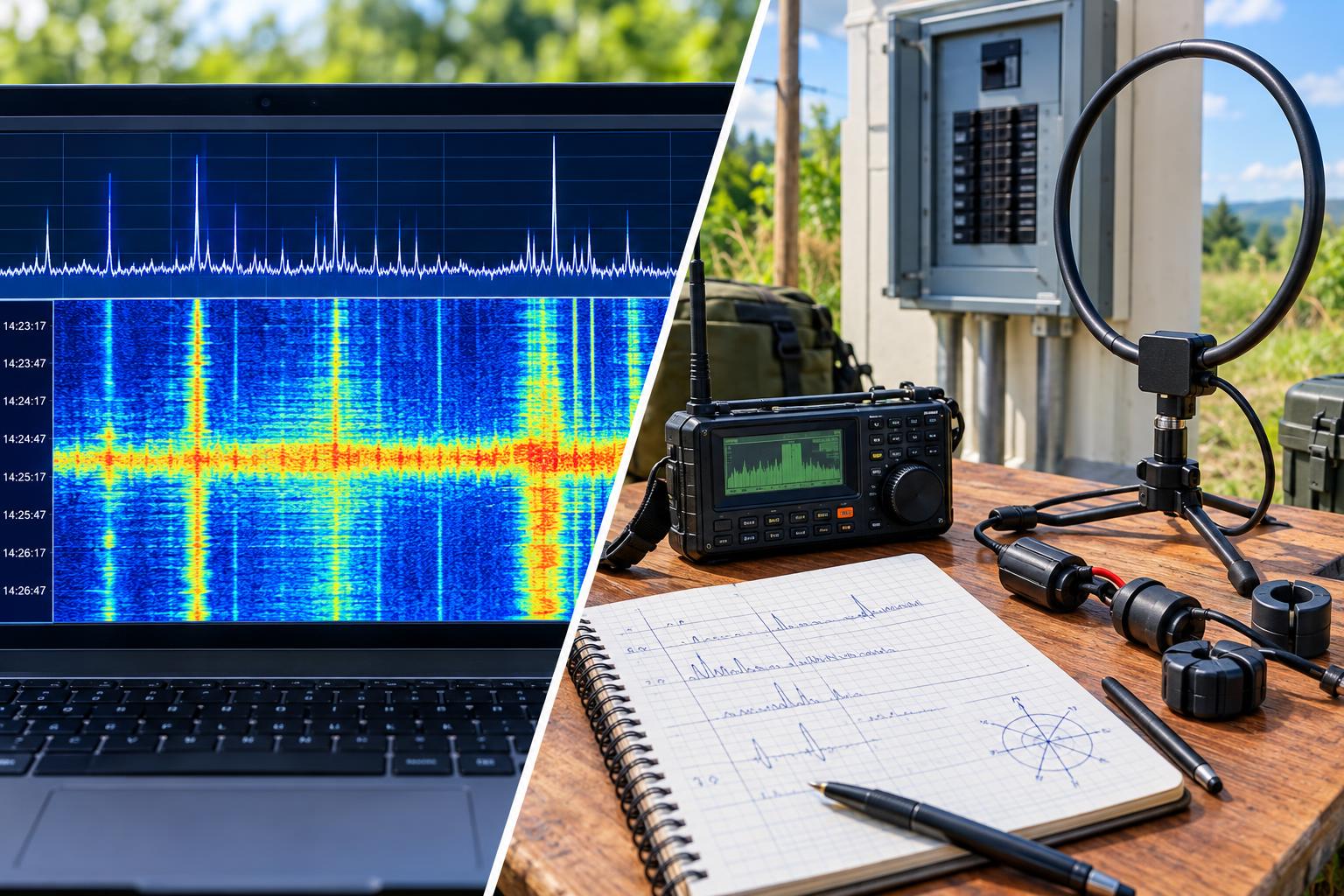
Find HF Noise with an SDR Waterfall: Breaker Test, RFI Log, Direction Finding, and When to Call the Utility

When your HF receive noise floor suddenly jumps, guessing is expensive and frustrating. A waterfall on an SDR or spectrum-scope-equipped transceiver can turn ham radio RFI troubleshooting into a repeatable process: observe the noise, isolate your own home, document what changes, and decide whether the next step is ferrites, a neighbor conversation, ARRL help, or a utility report.

The goal is not to accuse the first device, neighbor, or power pole that looks suspicious. The goal is to build a clean chain of evidence: what you saw, when it happened, what you turned off, where the signal peaked or nulled, and what recordings show. That kind of record is useful whether the source is a cheap switching supply in your shack, a solar inverter next door, or arcing hardware on the distribution line.

Start With a Baseline on the SDR Waterfall

Before touching breakers or ferrites, capture what the interference looks and sounds like. Set up the receiver so another operator could reproduce your observation.

  • Use a known antenna and band. Note the antenna, feed line path, preamp status, attenuator setting, RF gain, AGC setting, bandwidth, and mode.
  • Pick a quiet segment. Avoid strong broadcast stations, crowded contest activity, and local nets when you are trying to characterize broadband noise.
  • Save screenshots. Capture the waterfall with frequency scale, signal level scale if available, date, and time.
  • Record audio and I/Q if possible. A short AM-mode audio clip often reveals buzz, rasp, ticking, or arcing patterns more clearly than a still image.
  • Note the noise floor. If your software displays dBm or S-units, log the value, but remember that uncalibrated S-meters and SDR displays are comparative tools unless properly calibrated.

Waterfall clues are helpful but not conclusive. A wide raised floor may be common-mode noise arriving on your feed line. Narrow carriers may be electronics, networking gear, birdies, or legitimate signals. Repeating bands of hash every few kHz can suggest switching power supplies. Intermittent broadband bursts may point toward arcing, thermostats, motor controllers, chargers, or utility hardware.

Run the Home Isolation Breaker Test Correctly

The breaker test answers one critical question: is the source powered from your premises? Do this safely and methodically.

Preparation

  • Put the receiver, SDR, laptop, and any required network-free logging method on battery power.
  • If your station uses an active antenna, bias tee, antenna switch, preamp, rotator controller, USB hub, or external monitor, make sure each item is either intentionally battery-powered or disconnected for the test.
  • Tell other household members before shutting power off. Avoid interrupting medical equipment, security systems, sump pumps, or critical appliances.
  • Do not remove electrical panel covers or touch service conductors. Operate only normal breakers that you are competent and permitted to operate.

Procedure

  • Start the SDR waterfall and audio recording on the problem frequency.
  • Turn off branch breakers one at a time and pause long enough to see whether the waterfall changes.
  • If one breaker causes a major drop, leave it off briefly and identify the loads on that circuit.
  • If no branch breaker changes the noise, turn off the main breaker if it is safe and practical. Keep the receiver on battery.
  • Log every step with times: breaker off, breaker on, noise changed, no change.

If the noise disappears when a branch circuit is off, the source is likely on that circuit. If the noise remains with the main breaker off and your receive setup is truly isolated from house power, the source is probably external to your home or is being received directly by the antenna from an outside device. If the noise drops only when disconnecting USB cables, Ethernet cables, wall-wart chargers, monitors, or station accessories, you may be dealing with conducted noise entering through station wiring rather than radiated noise from a distant source.

Find In-House Sources Before Blaming the Antenna

Common household offenders include switching power supplies, LED lamps, dimmers, battery chargers, plasma or older electronic displays, variable-speed HVAC equipment, aquarium heaters, touch lamps, Ethernet-over-power adapters, garage door openers, and solar power electronics. In the shack, look at USB chargers, powered speakers, wall warts, computer monitors, cheap HDMI adapters, and noisy laptop supplies.

Once a suspect circuit is found, unplug devices rather than merely turning them off. Many appliances continue running standby supplies when apparently off. Watch the waterfall as each item is unplugged. The best evidence is an immediate, repeatable change: plug in, noise appears; unplug, noise disappears.

Use Ferrites Where They Actually Help

Ferrite chokes are useful when unwanted RF current is riding on the outside of coax shields, control cables, speaker leads, USB cables, DC power leads, or Ethernet cables. They do not repair a defective power pole, and they usually do not make a noisy device compliant by magic. They reduce a coupling path.

  • On receive feed lines: place common-mode chokes near the antenna feed point and near the receiver entrance when common-mode pickup is suspected.
  • On power and data leads: choke both conductors of a pair together so the ferrite sees common-mode current, not normal operating current.
  • Use multiple turns when practical: winding several turns through a suitable ferrite core often increases choking impedance at HF.
  • Confirm with A/B testing: install the choke, capture the waterfall, remove or bypass it if practical, and compare.

If ferrites reduce the noise only when placed on the receiver’s cables, your station wiring may be acting as an unintended antenna. If ferrites on the offending device’s leads reduce emissions, that may solve a household problem. For a neighbor’s device, diplomacy matters: provide clear observations, avoid accusations, and offer a simple test only if invited.

Build an RFI Log That Others Can Use

The American Radio Relay League’s RFI guidance emphasizes documentation, isolation tests, recordings, direction finding, and the use of tools such as SDRs, spectrum scopes, and audio analysis. Your log does not need to be fancy, but it should be consistent.

Minimum useful RFI log fields

  • Date and local time
  • Frequency, mode, bandwidth, and antenna
  • Receiver or SDR settings that affect level
  • Noise description: steady, pulsed, drifting, intermittent, weather-related, time-of-day pattern
  • Waterfall screenshot filename
  • Audio or I/Q recording filename
  • Breaker-test result
  • Direction-finding notes and map references
  • Weather conditions if power-line noise is suspected, especially wind, rain, dry conditions, or humidity changes

Audio editors such as Audacity can help visualize periodic buzzing or pulses, but avoid overclaiming. A 120 Hz buzz pattern may be consistent with arcing related to AC power, but it is not by itself proof of a specific pole or device. Treat every clue as part of a larger case.

Direction Finding: From Your Shack to the Street

Direction finding starts with a simple question: does the signal have a direction, or is it entering through wiring everywhere? For HF, a small portable loop, a battery-powered receiver, or a handheld SDR with a loop or whip can be more useful than a full-size base antenna.

Practical DF sequence

  • Confirm the signal on more than one frequency. Power-line-type noise is often broadband and may be audible across multiple HF bands.
  • Use AM mode. AM reception often makes impulse noise easier to hear and compare.
  • Reduce receiver gain. As you get closer, add attenuation or use a smaller antenna to avoid overload and false peaks.
  • Use nulls carefully. A loop antenna’s null can be sharper than its peak, but reflections and wiring can distort bearings.
  • Move in stages. Check your yard, then sidewalk or public areas, then compare bearings from multiple locations.

Do not enter private property, climb poles, open utility cabinets, touch guy wires, or get near energized equipment. Direction finding for utility noise is about locating likely evidence, not performing electrical work.

Recognizing Power-Line-Like Noise

Power-line interference is often broadband, harsh, raspy, and strongest on lower HF bands, though it can appear higher. It may vary with wind, moisture, temperature, and load. Dry, windy weather can aggravate loose or contaminated hardware; rain may temporarily quiet some sources or make others worse. Arcing sources can produce repetitive buzz, snapping, or frying sounds in AM audio.

IEEE Std 1897-2024 provides a recent standards reference for practices related to locating power-line interference, and ARRL maintains specific guidance on power-line noise. For the amateur operator, the practical takeaway is simple: utilities respond best to specific, repeatable observations, not vague reports that the bands are noisy.

When to Call the Utility

Contact the utility when you have reasonable evidence that the source is outside your home and associated with power distribution equipment. Useful evidence includes:

  • The noise remains with your main breaker off while the station is battery-powered.
  • The signal is heard on a portable receiver away from your house.
  • Bearings or walking tests repeatedly point toward the same pole, transformer area, or line section.
  • The noise changes with weather or wind in a way consistent with arcing hardware.
  • You have screenshots, recordings, dates, times, and frequencies.

When reporting, be concise and cooperative. Say that you are a licensed amateur radio operator experiencing radio-frequency interference, you have performed a home power isolation test, and you have observations suggesting a possible power-line noise source near a particular location. Do not demand that a line crew accept your diagnosis. Ask for an investigation by personnel who handle radio or power-quality interference complaints.

Regulatory and Neighbor Caveats

In the United States, the FCC has jurisdiction over radio-frequency interference issues, and many consumer electronic devices operate under rules that require them not to cause harmful interference. The FCC’s interference guidance is a useful background reference, but most problems are solved faster with good documentation and courteous cooperation than with threats.

For neighbor-related RFI, start with your own proof. Demonstrate that the noise is not from your house before approaching anyone else. If a specific device is suspected, ask for a short, convenient test rather than making accusations. Offer to share recordings or screenshots. If a manufacturer, landlord, solar installer, or utility becomes involved, your RFI log becomes the common technical language.

Example Workflow

Suppose 40 meters changes from a normal evening noise floor to a broad S7 hash with diagonal streaks on the waterfall. You capture screenshots at 7.180 MHz in AM and SSB, record 60 seconds of audio, and log the antenna and receiver settings. On battery power, you turn off branch breakers. The noise remains. You turn off the main breaker; the noise still remains. A portable receiver hears the same buzz on the sidewalk, and a small loop gives a consistent null pointing along the street. Two evenings later, the noise is worse in dry wind and quieter after rain. You now have a reasonable basis to continue DF from public areas and, if the evidence points to distribution equipment, contact the utility with a clear report.

By contrast, if the noise vanishes when the office breaker is off and returns when an LED desk lamp is plugged back in, the solution is local: remove the device, replace its supply, add appropriate chokes if effective, or relocate it away from station wiring.

Key Takeaways

  • Use the SDR waterfall as an evidence tool, not just a display.
  • Run the breaker test with the receiving setup on battery power.
  • Document screenshots, audio, settings, times, and weather.
  • Apply ferrites to reduce common-mode coupling, not as a cure-all.
  • Use safe, legal direction finding from your property and public areas.
  • Call the utility when the evidence points outside your home and toward power distribution equipment.

FAQ

Can an SDR waterfall prove the source of RFI?

Usually not by itself. A waterfall can show timing, bandwidth, drift, and relative strength, but source identification requires isolation tests, repeatability, and often direction finding.

Should I transmit while troubleshooting receive noise?

Normally no. Receive-noise troubleshooting is best done by listening, recording, and isolating. Transmitting adds variables and may create separate RF-in-the-shack issues.

Why does the noise change when I touch the coax or laptop?

That often suggests common-mode pickup or conducted noise through station wiring. Check bonding, cable routing, USB and power leads, and feed-line choking.

What if the utility says it cannot find anything?

Provide your log, recordings, dates, and location notes. Continue documenting patterns. If needed, consult ARRL RFI resources for guidance on organizing a more complete case.

Helpful References

Posted on — Leave a comment

APRS via the ISS in 2026: Check the Live Status, Correct Path, and One-Pass Workflow Before You Transmit

APRS via ISS: start with status, not the transmit button

APRS via ISS is one of the most satisfying short-pass activities in amateur radio, but it is also easy to do poorly. The International Space Station is not a full-time APRS repeater under your control. The packet system may be active, silent, temporarily reconfigured, reserved for an ARISS school contact, affected by maintenance, or simply not hearing your station during a particular pass.

Before transmitting, treat every pass as conditional. The correct first question is not “What power should I use?” It is “Is the ISS packet system active right now, and what do the current status pages show?”

For 2026 operating, the most useful official starting points are the ARISS APRS status page, the AMSAT live digipeater satellites page, AMSAT SatDB, and the long-running APRS ISS FAQ. As of this writing, the ARISS APRS page showed recent RS0ISS packet activity on November 11, 2026, and AMSAT’s digipeater satellite list had been updated October 31, 2026. Those dates are useful clues, not a promise that the next pass over your grid will be active.

The frequency and mode to program

For normal ISS APRS packet operation, the widely used setting is 145.825 MHz FM, 1200 baud AFSK packet. This is the same basic audio-frequency-shift-keying packet format used by classic terrestrial VHF APRS, but the operating style is different because the ISS is moving quickly and the shared access window is short.

Most operators leave the radio on 145.825 MHz for the pass. Doppler shift exists on 2 meters, but at 1200 baud FM packet it is usually manageable with a fixed frequency, especially on a decent pass. If your equipment supports satellite memory channels and you know how to use them, fine; if not, do not let Doppler tuning become the reason you miss the pass. A properly configured TNC, sound-card modem, handheld APRS radio, or mobile APRS transceiver on 145.825 MHz FM is the practical baseline.

Use normal packet audio levels. Overdriven AFSK is a common reason for failure. If you are using a sound-card interface, set the transmit audio so the radio reaches normal deviation without clipping or sounding harsh. If your radio has a data connector, it may provide more consistent results than speaker/microphone audio, but either can work if adjusted carefully.

The correct APRS path for ISS packet

For APRS via ISS, the practical path to use is:

  • ARISS

That is the key setting. Do not use terrestrial APRS paths such as WIDE1-1, WIDE2-1, or long multi-hop paths. They are not appropriate for the ISS digipeater and only add clutter or confusion. In many radios and TNC programs this field may be called “packet path,” “digipeater path,” “unproto path,” or simply “path.”

Your destination field may be set by the radio or software, often as APRS, CQ, or a device-specific APRS identifier. In most practical station setups, the path matters more than changing the destination field. If your manual or software profile has a known ISS/APRS satellite preset, verify that it uses ARISS and does not append terrestrial WIDE hops.

What a successful digipeat looks like

When the ISS digipeats your packet, you may see a received packet path containing the ISS station call sign with an asterisk, commonly shown in a form similar to RS0ISS*. The asterisk indicates the digipeater that repeated the packet. Exact display formats vary by radio, TNC, and web gateway, so do not rely on one visual style only. The important idea is that your packet came back through the ISS packet system, not merely that your own TNC transmitted something.

Which status source should you trust?

Status checking works best when you separate three different questions:

  • Is ISS packet generally listed as active? Check ARISS and AMSAT status pages.
  • Has the ISS packet station actually been heard recently? Look for recent RS0ISS packet activity on the ARISS APRS status page or other reputable APRS monitoring sources.
  • Is the pass favorable from my location? Use a current satellite pass predictor with your grid square or coordinates.

If one page says the ISS packet system is active but nobody has heard packets recently, listen first and transmit sparingly. If a status page is stale, do not assume failure or success; use it as one input. If ARISS announces a school contact, SSTV event, maintenance period, or other configuration change, that takes priority over an old memory channel in your radio.

AMSAT’s live digipeater list is also useful because it reminds operators that the ISS is not the only packet-capable spacecraft. If ISS packet is off, another listed digipeater satellite may be active. However, each satellite has its own frequency, mode, and path requirements. Do not copy the ISS path blindly to another spacecraft unless the current documentation says to do so.

A one-pass workflow before you transmit

A good APRS via ISS attempt is planned in minutes, not improvised in the middle of the pass. Use this workflow before every attempt.

1. Check current operating status

Open the ARISS APRS status page and the AMSAT digipeater status page. Confirm that ISS packet activity is currently expected or has been recently observed. If the status looks uncertain, plan to listen only until you hear the ISS packet downlink.

2. Pick a pass worth using

Choose a pass with enough elevation to give your station a real chance. A very low pass can work from a quiet location with a good antenna, but a higher pass is far better for learning. For a first attempt, favor a pass with a maximum elevation above about 30 degrees if one is available. Enter your correct grid square or location in your pass-prediction software; a pass listed for another city may not match your horizon.

3. Program the station before AOS

Before acquisition of signal, set the radio to 145.825 MHz FM, configure 1200 baud packet, set the path to ARISS, and prepare a short position packet or concise message. Confirm your call sign and SSID are correct. If you use beacon text, keep it brief and noncommercial.

4. Listen first

At AOS, listen. You may hear packet bursts before your software decodes them. If you hear repeated ISS packets or see stations being digipeated, the system is active on that pass. If you hear nothing, avoid filling the channel with repeated blind transmissions. The ISS may be below your usable horizon, blocked by terrain, or not in packet mode.

5. Transmit sparingly near the best part of the pass

The shared channel can become congested. One or two well-timed packets are better than rapid beaconing. Transmit near the stronger part of the pass, often around mid-pass or near maximum elevation, unless you have a specific reason to try earlier. If your radio automatically beacons every minute on terrestrial APRS, disable that behavior for satellite work and send manually or with a conservative satellite profile.

6. Confirm after the pass

Do not assume success because your radio transmitted. Confirm that the packet was actually digipeated. Check your radio’s received packet list, TNC monitor window, local recording, second receiver, or APRS-IS-derived display. Look for your call sign associated with an ISS digipeater path such as RS0ISS being marked as used. If you only see your locally transmitted packet and no repeated path, it was not confirmed via ISS.

Station examples that can work

A handheld APRS transceiver with a stock antenna may decode strong passes, but it is not the most reliable uplink station. A better simple setup is a handheld or mobile VHF radio feeding a small directional antenna such as an Arrow-style handheld Yagi, an Elk log periodic, or another suitable 2-meter antenna. Even a modest antenna helps overcome path loss and body shielding.

A mobile APRS radio at 25 to 50 watts into an outdoor vertical can work on favorable passes, but vertical antennas are not ideal at every satellite elevation angle. A sound-card TNC with a laptop and FM transceiver can also work well if transmit audio, receive audio, PTT control, and timing are configured before the pass.

Power is not a substitute for clean audio and good timing. Excessive power into a poor antenna can still fail, while moderate power into a properly aimed antenna can be effective. Use the minimum power that reliably supports communication and remains consistent with good amateur practice and RF exposure requirements.

Common reasons ISS APRS attempts fail

  • The packet system was not active. The ISS radio may have been in another mode or unavailable.
  • The path was wrong. Use ARISS, not WIDE paths.
  • The pass was too low. Buildings, terrain, trees, and vehicle roofs can block VHF signals.
  • The channel was congested. Too many stations transmitting at once can cause collisions.
  • AFSK audio was overdriven or too low. Packet may sound present but fail to decode.
  • The operator transmitted too often. Repeated beacons increase collisions and reduce everyone’s chance.
  • The station never confirmed the downlink. Hearing yourself transmit is not the same as being digipeated.

Operating courtesy and regulatory reminders

In the United States, transmit only within your amateur license privileges and follow FCC Part 97 requirements, including station identification and noncommercial content. Operators outside the United States must follow their own national rules. Space station operation can also involve additional practical constraints, so current ARISS and AMSAT guidance should take precedence over old notes or saved radio memories.

Keep transmissions short. Avoid unnecessary bulletins, long free-text messages, unattended rapid beaconing, experiments that monopolize the pass, or attempts to use the ISS as an ordinary terrestrial APRS fill-in digipeater. Hundreds of operators may be within the footprint during a good pass, and the usable window may be less than ten minutes.

Also consider safety. If using a handheld directional antenna outdoors, stay aware of traffic, footing, weather, power lines, and trip hazards. For higher-power fixed or mobile stations, evaluate RF exposure, coax routing, grounding, and lightning protection as appropriate. Do not aim an antenna or manage a laptop while driving.

Quick checklist for APRS via ISS

  • Check ARISS and AMSAT status before the pass.
  • Use 145.825 MHz FM for normal ISS APRS packet operation.
  • Set 1200 baud AFSK packet.
  • Set the packet path to ARISS.
  • Remove WIDE1-1, WIDE2-1, and other terrestrial APRS paths.
  • Choose a favorable pass and know AOS, maximum elevation, and LOS.
  • Listen first; transmit only if the pass and status make sense.
  • Send one or two concise packets, not a stream of beacons.
  • Confirm the digipeat by checking for an ISS-used path such as RS0ISS*.
  • If it fails, change one variable at a time: status, pass elevation, antenna, audio level, or timing.

FAQ

Can I use my normal APRS beacon settings?

Usually not without adjustment. Terrestrial APRS settings often use WIDE paths and automatic beacon intervals that are unsuitable for the ISS. Create a separate satellite profile using ARISS as the path and conservative manual or infrequent transmission.

Do I need full-duplex operation?

Full-duplex reception is helpful because you can hear whether the ISS is active while transmitting or immediately afterward, but many APRS attempts are made with half-duplex radios. If you cannot hear your own digipeated packet, confirm after the pass through received logs, a second receiver, or reliable networked packet reports.

Should I transmit if I do not hear the ISS?

For routine operation, listening first is the better practice. If the status pages show recent activity and the pass is strong, a single carefully timed attempt may be reasonable, but repeated blind transmissions are poor operating practice.

What is the most important setting?

After confirming that ISS packet is active, the most important station setting is the path: ARISS. The next most important practical factors are clean 1200 baud audio, a usable antenna, and restrained timing.

Key takeaways

APRS via ISS is not difficult, but it rewards disciplined operating. Check live status first, program 145.825 MHz FM 1200 baud packet, use the ARISS path, pick a worthwhile pass, listen before transmitting, and confirm that your packet was actually repeated through the ISS. A single clean, well-timed packet is far more useful than a burst of hopeful beacons.