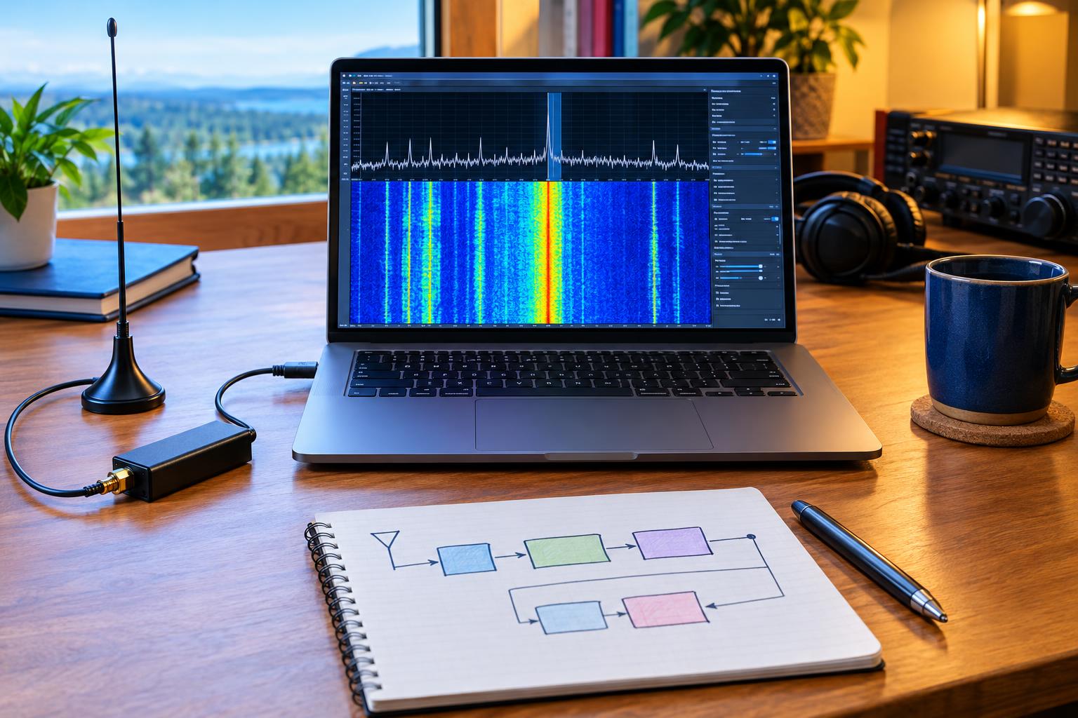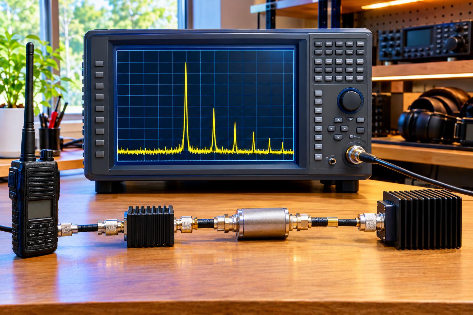
Posted on — Leave a comment

Port One SDR Flowgraph to GNU Radio 4 RC3: Benchmark It Without Risking Your 3.10 Station Setup

Why Test GNU Radio 4 RC3 Without Touching Your Working Station?

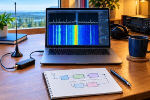
GNU Radio 4.0.0-RC3 was released on October 13, 2026, as a release candidate for the next major generation of GNU Radio. The project’s release information describes changes across the runtime, scheduler, blocks, and Studio, while the GNU Radio 3.x line remains the stable choice for many active stations. For a ham operator who relies on GNU Radio 3.10 for known-good SDR work, that creates a practical question: how do you explore the new toolchain without breaking the station setup that already copies satellites, decodes weak signals, watches band activity, or records IQ during an opening?

The safest answer is not to migrate your whole shack at once. Port one carefully chosen SDR flowgraph, run it in isolation, feed it repeatable IQ data, and compare behavior against your existing GNU Radio 3.10 result. This gives you useful information about the GNU Radio 4 RC3 ham SDR workflow without putting your regular operating setup, device permissions, out-of-tree modules, or configuration files at risk.

This article focuses on receive-side SDR and spectrum-analysis flowgraphs, because they are ideal for controlled testing. If your flowgraph has any transmit, PTT, amplifier control, or antenna switching behavior, treat it as a higher-risk project and keep RF hardware disconnected until you have verified every control path.

Start With the Right Flowgraph

Choose a flowgraph that is meaningful but not mission-critical. A good first candidate is a receive-only spectrum display, FM demodulator, SSB monitor, NOAA weather radio receiver, APRS audio monitor, or saved-IQ analyzer. Avoid your largest contesting, EME, satellite Doppler, or multi-radio automation flowgraph as the first port.

The best first flowgraph has these traits:

  • Receive-only operation: No transmit chain, PTT line, relay driver, or amplifier control.
  • Few hardware dependencies: One SDR source is easier than multiple synchronized devices.
  • Repeatable input: It can run from a file source as well as a live SDR.
  • Clear outputs: You can compare a spectrum, audio stream, decoded symbols, waterfall behavior, or output file.
  • Limited custom code: Built-in blocks are easier to replace or re-create than several custom embedded Python blocks.

If your station flowgraph currently receives 20 meters SSB, monitors 2 meters FM, or records a slice of the HF spectrum, make a stripped-down copy. Remove logging uploads, rig control, rotator control, network publishing, and anything else not needed for the first benchmark. Your goal is not to prove that every station function ports immediately. Your goal is to learn how the new runtime and block model affect one real use case.

Protect the GNU Radio 3.10 Environment First

Before installing or building anything related to GNU Radio 4 RC3, make a small station-preservation plan. Many GNU Radio problems are not caused by the flowgraph itself; they come from overwritten Python paths, changed environment variables, conflicting shared libraries, or package-manager upgrades that replace a working version. Isolation matters.

Use a Separate Test Environment

The safest options are a separate computer, a virtual machine, a container, or a separate boot drive. A second machine is simplest if you already have one available. A virtual machine is excellent for file-based benchmarking and learning the interface, although direct USB SDR access can be less predictable. A container can be efficient for advanced users, but it requires care when passing SDR devices, audio, graphics, and USB permissions through to the container.

If you test on the same computer that runs GNU Radio 3.10, do not casually replace distribution packages. Use a separate install prefix, separate shell environment, and separate user configuration directory where possible. Do not add experimental library paths globally in your shell startup files. If you must set environment variables, put them in a dedicated launch script for the test environment only.

Back Up What Actually Matters

Back up more than the visible flowgraph file. Save your GNU Radio 3.10 flowgraphs, custom block source code, Python helper scripts, udev rules, device serial mappings, rig-control settings, audio routing notes, and any systemd user services or startup scripts. If your station depends on a particular SDR serial number or gain setting, record it. A written recovery note is often more useful than a vague memory of how the station was configured.

Make a Repeatable IQ Test Signal

Benchmarking a live antenna input is tempting, but propagation and band occupancy change constantly. A receiver that looks better at 0100 UTC than it did at 2300 UTC may simply be seeing a different band. For fair comparison, capture an IQ recording with the existing 3.10 setup and use that same file as input to the GNU Radio 4 RC3 experiment.

Pick a signal that matches the flowgraph’s purpose. For a spectrum-analysis flowgraph, record a few minutes of a band segment with several visible carriers. For FM demodulation, record a local repeater, NOAA weather station, or other signal you are legally allowed to monitor. For HF SSB receive testing, record a stable voice signal plus adjacent-band noise so you can judge filtering and tuning behavior. Keep sample rate, center frequency, sample format, and gain settings documented.

A useful test note might include: SDR model, antenna or dummy source, center frequency, sample rate, RF gain, bandwidth, file format, date and time, and whether the signal was live off-air or generated inside the receiver chain. Do not rely on memory. A benchmark is only repeatable if the input and assumptions are written down.

Rebuild the Flowgraph, Don’t Blindly Convert It

Major-version release candidates are not the place to assume that every block, parameter, or scheduler behavior maps one-for-one. Treat the port as a reimplementation of the signal path, not just a file conversion. Draw the old flowgraph as a simple chain: source, frequency translation, filtering, resampling, demodulation, visualization, audio, file sink, or decoder. Then rebuild the same chain in the RC3 environment using the available blocks and current documentation.

For many ham SDR flowgraphs, the essential logic is straightforward:

  • Source: file source for the benchmark phase; live SDR source later.
  • Rate control: throttle only when there is no hardware clock or real-time sink controlling the rate.
  • Tuning: frequency translating filter or equivalent frequency shift and filter stage.
  • Filtering: low-pass, band-pass, or channel filter matched to the mode.
  • Demodulation: FM, AM, SSB, CW audio, or digital-mode preprocessing as applicable.
  • Output: spectrum, waterfall, audio sink, WAV file, or decoded stream.

Keep the first RC3 version boring. Use fixed parameters. Skip optional GUI controls until the signal path works. Once the basic chain is stable, add variables, sliders, and live controls one at a time. When something fails, you will know which change caused it.

Benchmark What Matters to a Ham Operator

A useful benchmark does not have to be elaborate. It should answer practical station questions: does the flowgraph start reliably, keep up in real time, show the expected spectrum, produce intelligible audio, and avoid overruns or dropouts? For spectrum work, also check whether frequency offsets, bin spacing, and displayed bandwidth match expectations.

Compare These Items

  • Startup behavior: Does the flowgraph launch cleanly, or are there missing blocks, parameter errors, or device-access failures?
  • CPU load: Compare approximate CPU use under the same sample rate and visualization settings.
  • Memory behavior: Watch for steady growth during a longer run, which may indicate buffering or sink problems.
  • Real-time performance: Look for underruns, overruns, choppy audio, or a waterfall that falls behind.
  • Frequency sanity: Confirm that known carriers appear at the expected offset from center.
  • Audio quality: Compare level, distortion, muting, latency, and filter response using the same IQ file.
  • Output files: If the flowgraph writes audio or IQ, verify sample rate, duration, and file format.

Do not claim a broad performance result from one experiment. A single ham workstation, one SDR, and one flowgraph tell you about that configuration only. The value is still real: you learn whether your own workload is promising enough to continue testing.

A Practical Porting Example: 2 Meter FM Monitor

Suppose your GNU Radio 3.10 station has a simple 2 meter FM receive flowgraph. It uses an SDR source centered near a local repeater output, a frequency translating filter, FM demodulation, de-emphasis if needed, squelch, audio output, and a waterfall. To test this safely in RC3, first record IQ from the 3.10 system while the repeater is active. Then create a test version that uses the IQ file source instead of the SDR hardware.

Document the original sample rate and center frequency. If the repeater signal was 25 kHz above center, verify that the RC3 flowgraph shifts and filters that same offset. Use a channel filter wide enough for the signal you are analyzing, but not so wide that adjacent signals dominate the demodulator. Run the file through both versions and compare whether the audio begins at the same point, whether levels are similar, and whether the waterfall shows the carrier in the same place.

Only after the file-based version behaves sensibly should you try live hardware. When you do, connect receive-only hardware first. If your SDR can transmit, disable or disconnect transmit capability, use a dummy load where appropriate, and confirm that no control line can key a transmitter unexpectedly.

Handling Out-of-Tree Blocks and Custom Code

Many mature ham stations depend on out-of-tree modules, custom Python blocks, or small helper programs written over several years. These are often the slowest part of a major-version evaluation. Make an inventory before porting. Mark each item as essential, replaceable, or optional.

For the first test, replace optional custom blocks with built-in equivalents or file sinks. If a custom block performs logging, network reporting, or station automation, remove it from the benchmark path. If it performs actual DSP that you need, write down the mathematical function it provides. Sometimes a custom block exists because an older flowgraph needed a convenience wrapper, not because the DSP is unique.

When custom code is required, port it separately from the full flowgraph. Feed it a short known file, check its output, then insert it into the larger chain. This avoids the frustrating situation where a scheduler issue, a type mismatch, and a GUI problem all appear at once.

Safety and Regulatory Caveats

Software-defined radio can control real RF hardware. That means a software experiment can become a station-safety problem if it keys a transmitter, changes frequency unexpectedly, drives an amplifier, or bypasses normal interlocks. For receive-only testing, the risk is much lower, but you should still avoid connecting experimental software to unattended station control.

For any transmit-capable SDR, keep RF output terminated in an appropriate dummy load until you have verified frequency, power, modulation, and PTT behavior. Observe FCC amateur rules, your license privileges, band limits, RF exposure requirements, and local electrical and antenna-safety practices. Technical capability is not the same as operating permission. If your station uses shared antennas, remote operation, preamps, mast-mounted gear, or lightning protection, do not let a software test bypass established safeguards.

When to Keep Using 3.10

There is no shame in keeping GNU Radio 3.10 as your production station while you evaluate RC3. In fact, that is the responsible approach for most active operators. Continue using the stable setup for scheduled nets, contests, satellite passes, POTA spotting, weak-signal work, or emergency-communications support. Use RC3 as a learning and evaluation environment until the specific blocks, hardware interfaces, and workflows you need are ready for your station.

A good migration decision is evidence-based. If the RC3 port runs the same IQ files correctly, handles live receive without dropouts, supports your necessary hardware, and can be restored or rebuilt from notes, you may decide to port more flowgraphs. If not, you have still learned something valuable without damaging the station that already works.

Key Takeaways

  • Test GNU Radio 4 RC3 in an isolated environment rather than modifying your working GNU Radio 3.10 station.
  • Port one receive-only flowgraph first, preferably one that can run from a recorded IQ file.
  • Benchmark with repeatable inputs, not changing band conditions.
  • Compare startup behavior, CPU use, real-time performance, frequency accuracy, audio, and output files.
  • Keep transmit-capable hardware disconnected or safely terminated until all control behavior is verified.
  • Use the RC3 experience to make an informed migration plan, not a rushed replacement.

FAQ

Is GNU Radio 4 RC3 meant to replace my 3.10 station immediately?

Not automatically. RC3 is a release candidate for the GNU Radio 4 line, while many operators still depend on 3.x for stable station work. Treat RC3 as an evaluation platform until your specific hardware, blocks, and workflows are proven.

Can I run GNU Radio 3.10 and GNU Radio 4 RC3 on the same computer?

It may be possible, but isolation is strongly recommended. Use a separate machine, virtual machine, container, boot drive, or carefully separated install prefix and environment. Avoid global changes that could alter Python paths, shared libraries, or device access used by 3.10.

What is the safest first benchmark?

A file-source replay of a recorded IQ sample is usually safest. It removes propagation changes, avoids immediate hardware-access problems, and lets you compare the same signal path in both versions.

Should I test with live SDR hardware?

Yes, but only after the file-based flowgraph works. Start with receive-only operation. For transmit-capable SDRs, disconnect antennas, use appropriate dummy loads, verify PTT behavior, and follow applicable amateur-radio regulations.
Helpful References

Posted on — Leave a comment

HADES-L Reality Check: Verify Telemetry, Doppler, and 29.472 MHz Uplink Etiquette Before Transmitting

Why HADES-L Deserves a Careful First Pass

The HADES-L amateur satellite is exactly the kind of new low Earth orbit opportunity that gets operators excited: fresh reports, fresh orbital data, and the possibility of hearing an amateur payload that was not on your pass list a short time ago. The responsible way to approach any new LEO, however, is not to transmit first and sort out the details later. It is to verify the satellite is active, confirm the current operating mode, understand Doppler behavior, and make sure your license privileges cover the uplink you plan to use.

The research trail for HADES-L is useful but also a reminder that satellite operations are time-sensitive. The IARU satellite frequency coordination page lists HADES-L as coordinated on 2026-10-02, AMSAT reported October Transporter-18 amateur payload activity in its November 2026 news archive, and AMSAT SatDB lists HADES-L as active. Those are good starting points, not a substitute for current pass-by-pass verification. A coordinated frequency plan does not prove the payload is enabled on your next pass, and an active database entry does not mean the transponder is open at all times.

Before transmitting, treat HADES-L as a live shared resource. Listen, decode if possible, verify current status from trusted sources, and operate as if every unnecessary carrier blocks someone else’s one chance at the pass.

Start With Source Verification, Not Software Memory

Satellite tracking programs are only as good as the data and frequency memories you feed them. If you imported HADES-L once, or copied a frequency note from a social post, do not assume it remains correct. Commissioning phases, mode changes, experimental schedules, and naming updates can all affect what you should do on the air.

Use authoritative references first:

Read those sources with the right mindset. The IARU coordination entry helps identify the intended frequency plan. AMSAT news can confirm launch and amateur payload activity. SatDB can help with current status and satellite identification. The ARRL Letter can provide broader amateur-radio context. None of these should be treated as permission to transmit blindly. Your station, your country, your license class, and the satellite’s current status still matter.

Confirm the Uplink Before You Key the Microphone

The title frequency, 29.472 MHz uplink, sits in the 10-meter band. That has two important consequences for US operators. First, it is HF, not VHF or UHF, so your transceiver, antenna system, filtering, and RF exposure assumptions may differ from a typical 2-meter or 70-centimeter satellite setup. Second, US license privileges are not identical across the entire 10-meter band.

In the United States, operators must check current FCC amateur rules and their license class before transmitting. Do not assume that holding a Technician license automatically covers 29.472 MHz. Technician HF privileges are limited compared with General, Advanced, and Amateur Extra privileges, and 29.472 MHz is not in the familiar Technician 28.0 to 28.5 MHz segment. International operators should check their own regulator and band plan.

Also verify the mode. Do not assume the uplink is FM, SSB, data, or a specific signaling format unless a current source says so. A wrong-mode transmission can be just as disruptive as an off-frequency one. If a satellite uses an uplink access tone, data protocol, or scheduled activation window, that information must come from current operational guidance, not from guesswork.

Telemetry First: Hear the Satellite Before You Use It

For a new LEO, the best first contact is often no contact at all. Start by receiving. If HADES-L is sending telemetry, a beacon, or any published downlink signal, confirm that you can hear or decode it before attempting an uplink. This tells you several things at once: your tracking data is close, your pass prediction is reasonable, your receive chain works, and the satellite is actually present during that pass.

A practical receive-only check looks like this:

  • Update your Keplerian elements or TLE source before the operating session.
  • Confirm the satellite name, NORAD catalog number if available, and any alternate object naming in your tracking program.
  • Choose a pass with adequate elevation. A higher pass gives more time and a stronger signal margin.
  • Record the pass audio or baseband if your setup allows it, so you can review weak telemetry later.
  • Note the actual acquisition of signal and loss of signal times compared with prediction.
  • Do not transmit if you cannot positively identify the satellite or its active mode.

Telemetry is more than a courtesy. It is your reality check. If the downlink is absent, unstable, or inconsistent with current reports, that is a reason to wait, not to call harder.

Doppler: The Uplink Is Low, but the Pass Is Still Moving

Doppler shift is unavoidable with LEO satellites. The satellite is moving several miles per second relative to your station, so the apparent frequency changes during the pass. On a 29.472 MHz uplink, Doppler is much smaller than it would be on 145 MHz or 435 MHz, but it is not zero. A simplified maximum estimate is:

Doppler shift = frequency × relative velocity ÷ speed of light

Using 29.472 MHz and an illustrative LEO relative velocity of about 7.5 km/s, the maximum possible shift is roughly 737 Hz. In real operation, the shift varies through the pass and depends on geometry. That amount may be small compared with a wide FM channel, but it matters for narrowband or data modes and for disciplined operating. The downlink, if it is on VHF or UHF, may show a much larger Doppler shift and usually deserves more active correction.

Do not rely on a single fixed frequency memory unless the published operating method says that is appropriate. Many satellite operators use computer-assisted Doppler correction through CAT control. Others manually tune the higher-frequency side of the path while keeping the lower-frequency side more stable. The correct strategy depends on the satellite’s mode and published operating convention.

29.472 MHz Uplink Etiquette on a Shared Pass

A LEO pass is short. The usable window may be only a few minutes, and dozens of stations may be hearing the same opportunity. Good uplink etiquette is not about sounding polished; it is about leaving room for the satellite and other operators.

Use these habits before calling HADES-L:

  • Listen through the first part of the pass. Confirm the downlink, the activity level, and whether stronger stations are already using the satellite.
  • Use the minimum effective power. More power is not better if it overloads the receiver or captures the channel. Increase only if you have a clear reason.
  • Keep calls short. Use your call sign, grid square if appropriate, and brief exchanges. Avoid long explanations during a busy pass.
  • Do not tune up on the uplink. Test antennas, SWR, audio levels, and CAT control into a dummy load or off-air method before the pass.
  • Avoid blind carriers. Repeated unmodulated keying to see if you can hear yourself is poor form and may block valid traffic.
  • Respect mode and schedule limitations. If the payload is in telemetry-only, commissioning, or restricted testing, do not attempt contacts.

The 10-meter uplink adds another concern: terrestrial propagation. Depending on band conditions, your signal may travel far beyond your local area even without the satellite. Make sure your transmitted audio, occupied bandwidth, and frequency accuracy are suitable for the band segment and mode.

Station Setup Checks Before the Pass

A safe HADES-L attempt begins before the satellite rises. Build a written checklist so you are not making avoidable decisions under time pressure.

Receiver side

  • Tracking software updated and time synchronized.
  • Correct satellite selected, with current TLE data.
  • Downlink frequencies entered from current references.
  • Recording enabled if desired.
  • Headphones or speaker level set before acquisition of signal.
  • Rotator, handheld antenna, or fixed antenna plan ready.

Transmitter side

  • License privileges confirmed for 29.472 MHz and intended mode.
  • Transmit frequency and offset plan verified.
  • Power set low initially, with no speech processor or excessive audio drive.
  • Microphone gain checked locally before the pass.
  • Antenna matched for 10 meters; feed line and connectors inspected.
  • RF exposure compliance considered for your antenna location and power.

For a 10-meter uplink, a full-size antenna is physically larger than the compact antennas many operators use for VHF/UHF satellite work. A quarter-wave vertical is roughly 8 feet long before adjustment, and a half-wave dipole is roughly 16 feet tip to tip. Portable operators should secure masts and wires so the desire to catch a pass does not create a trip, fall, or overhead-line hazard.

Worked Example: A Conservative First HADES-L Session

Suppose a US General-class operator wants to evaluate HADES-L from a home station. The station has an HF transceiver capable of 10 meters, a 10-meter antenna with acceptable SWR, and a separate SDR receiver for the expected downlink. The operator has current tracking data and has checked the IARU coordination entry, AMSAT news, and SatDB status.

For the first pass, the operator does not transmit. They record the downlink, watch the Doppler trend, compare actual signal timing with the predicted pass, and confirm whether the received signal matches current reports. If the downlink is not heard, they stop there. No uplink calls are made.

On a later higher-elevation pass, after confirming active operation and mode, the operator prepares a short call. Power is set conservatively. The operator listens first, waits for a clear opening, sends one brief call, and then listens on the downlink rather than repeating continuously. If no return is heard, the operator adjusts within the published Doppler plan and tries again only if the channel is clear. If the pass is crowded, the operator logs reception only and leaves the satellite to others.

That is not a timid approach. It is how experienced satellite operators protect a shared resource.

Common Mistakes to Avoid

  • Using old frequency memories. Always compare your radio memories with current published information.
  • Assuming active means available. A satellite can be active for telemetry while not open for general QSOs.
  • Ignoring license class limits. Technical ability to transmit on 29.472 MHz is not the same as legal authority.
  • Overdriving the uplink. Excessive power or audio can reduce usability for everyone.
  • Chasing the wrong object. New payloads may have confusing early names in tracking software. Verify identity.
  • Letting automation run unchecked. CAT Doppler correction is useful, but wrong settings can move you off frequency quickly.

FAQ

Is IARU coordination the same as permission to transmit?

No. IARU satellite frequency coordination identifies a coordinated frequency plan. Your authority to transmit comes from your license, regulator, operating rules, and the satellite’s current operating status.

Should I call HADES-L if I cannot hear the downlink?

Usually no. If you cannot confirm the satellite is present and active, transmitting increases the risk of interfering with other users or calling into the wrong situation.

Does Doppler matter on a 29.472 MHz uplink?

Yes, but less than on VHF or UHF. The 10-meter uplink Doppler is comparatively small, while a VHF or UHF downlink may require more correction. Follow the current operating guidance for the satellite’s mode.

Can a US Technician-class operator use the 29.472 MHz uplink?

Do not assume so. US Technician HF privileges are limited and do not generally include all of 10 meters. Check the current FCC rules and your license privileges before transmitting.

Key Takeaways

  • Verify HADES-L status from trusted sources before transmitting.
  • Use telemetry and downlink reception as your first reality check.
  • Confirm that 29.472 MHz is legal for your license class and jurisdiction.
  • Account for Doppler, especially on any VHF/UHF downlink.
  • Use minimum effective power, short calls, and courteous pass management.
  • When in doubt, listen and log rather than transmit.

The HADES-L amateur satellite can be a rewarding new LEO target, but the best operators approach it with discipline. Confirm the facts, respect the uplink, and make your first transmission only after the satellite, your station, and your privileges all check out.

Posted on — Leave a comment

Used Radio Listings After the 2026 FCC-ID Rule: Check Ham-Band-Only Gear Before You Buy or Sell

What changed for used radio listings in 2026?

On October 13, 2026, new FCC marketplace listing requirements took effect for certain radiofrequency devices offered through online marketplaces. For hams, the practical question is not simply “Does this radio have an FCC ID?” It is “Is this particular item required to have one, and does the listing describe the device accurately enough to avoid trouble for the buyer, seller, and station?”

The issue matters because amateur radio equipment sits in an unusual place. Many amateur transmitters intended only for operation in the Amateur Radio Service are not approved in the same way as consumer Wi-Fi routers, FRS handhelds, GMRS radios, Part 90 land-mobile radios, or CB equipment. ARRL reported that eBay restricted certain radio-equipment listings while exempting ham-band-only gear. That exemption is important, but it does not mean every radio marketed to hams is automatically exempt from FCC ID concerns.

This guide focuses on practical marketplace checks for FCC ID ham radio equipment sales, especially used transceivers, amplifiers, handhelds, power supplies, SDRs, and accessories that may affect station setup and interference.

FCC ID is not the same thing as legal amateur operation

An FCC ID is an equipment authorization identifier. It normally appears on devices that have gone through an FCC authorization process, such as certification. It is not a ham license, not proof that you may transmit anywhere the radio can tune, and not a guarantee that the equipment will be clean in your station after years of use or modification.

For amateur operators, a separate rule still applies: you are responsible for operating within your license privileges, using appropriate emissions, avoiding harmful interference, and meeting RF exposure requirements. A radio may have an FCC ID and still be illegal to use on a service for which you are not licensed. Conversely, a genuine amateur-band-only transmitter may not show an FCC ID because amateur transmitting equipment has different equipment authorization treatment than many consumer radio services.

First check: is it truly ham-band-only?

The key marketplace distinction is whether the device is limited to amateur bands or whether it can transmit outside them. Before buying or listing, identify the transmit capability, not just the receive coverage.

Common ham-band-only examples

  • HF amateur transceivers intended for 160 through 10 meters, sometimes including 6 meters, with transmit restricted to amateur allocations.
  • VHF/UHF mobile or handheld amateur transceivers limited to 2 meters, 70 centimeters, or other amateur bands.
  • Amateur-specific QRP kits and home-station radios designed only for Part 97 operation.

Examples that deserve closer scrutiny

  • Handhelds or mobiles advertised for “ham, business, public safety, GMRS, FRS, marine, and airband transmit.” Multi-service transmit claims are a warning sign.
  • “Unlocked,” “wideband transmit,” “MARS/CAP modified,” or “export” radios. A modification may be legal for a narrow purpose but misleading or unlawful when advertised broadly.
  • Radios that look like amateur gear but are actually Part 90 land-mobile radios, CB radios, GMRS radios, or software-defined transmitters capable of operation outside amateur allocations.

  • RF amplifiers, signal boosters, and transmit accessories. These may have different marketing and authorization issues than a basic ham transceiver.

If a listing says only “works on all frequencies,” that is not a selling point. For a ham buyer, it is a reason to ask detailed questions.

Buyer checklist before clicking “buy”

A clean listing should help you answer three questions: what is the device, what frequencies can it transmit on, and what condition is its RF output likely to be in?

1. Ask for the exact model and rear-panel label

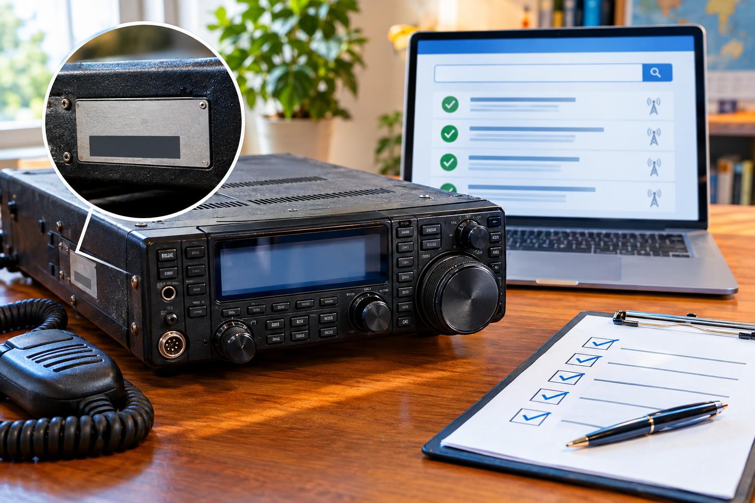
Model names can be confusing. One radio family may include several variants for different markets. Ask for a clear photo of the manufacturer label, serial-number area with private details obscured if desired, and any FCC ID label if present. If there is an FCC ID, compare it with the device model and description rather than relying on a blurry photo or seller claim.

2. Separate receive coverage from transmit coverage

Many amateur radios receive outside the ham bands. Wide receive coverage is common and usually not the issue. The concern is transmit capability. A listing for a used 2-meter/70-centimeter handheld should clearly indicate whether it transmits only on amateur bands or has been modified for broad transmit coverage.

3. Watch for misleading “no license needed” claims

Amateur transmitting requires the appropriate amateur license. A listing that promotes a ham transceiver as license-free, police/fire capable, or suitable for business dispatch should be treated cautiously. Even if the hardware is real, the seller may not understand the regulatory distinction.

4. Consider age, modifications, and RF cleanliness

Used gear can be electrically tired. Final transistors, low-pass filters, transmit/receive relays, shielding, and internal grounding can degrade or be damaged by poor repairs. An FCC ID, where applicable, does not prove a 20-year-old used radio still meets its original performance. If the seller cannot demonstrate basic operation, assume you may need bench work.

5. Think about interference before the box arrives

A bargain radio can become expensive if it causes TVI, audio interference, noise on your own receiver, or neighbor complaints. Plan your station as a system: radio, power supply, bonding, feed line, antenna, computer, USB cables, and nearby consumer electronics.

Seller checklist for accurate used ham listings

If you are selling used amateur equipment, your goal is a clear, narrow, factual listing. Do not overstate coverage, hide modifications, or borrow language from another seller’s listing.

  • State the intended service: “Amateur Radio Service transceiver” is clearer than “walkie-talkie for all uses.”
  • List transmit bands accurately: Example: “Transmits on 144–148 MHz and 420–450 MHz for licensed amateur use,” if that is correct for the unit.
  • Disclose modifications: If the radio has been widebanded, repaired, aligned, or altered, say so. If you do not know, say that instead of guessing.
  • Include FCC ID when present: If a device has an FCC ID label, include it accurately. Do not invent one, copy one from a similar model, or list an FCC ID for an accessory as if it belongs to the transmitter.
  • Do not imply unauthorized uses: Avoid claims such as “works on police channels,” “business radio,” “GMRS without paperwork,” or “no license required” unless the device and service rules truly support that statement.
  • Describe condition honestly: “Receives, transmits into dummy load, power output not laboratory verified” is better than “perfect” when you have not measured spurious emissions, frequency accuracy, or full power across bands.

How this affects station setup and interference

Marketplace compliance and station performance are linked. The same sloppy listing language that hides a questionable transmitter may also hide a radio that is more likely to create interference.

Used HF transceiver example

Suppose you find a used 100-watt HF transceiver listed as “opened for all bands.” Ask what that means. If it was modified for out-of-band transmit, you need to know whether the modification affected filtering, band switching, or alignment. For legal ham operation you still transmit only where permitted by your license. For station cleanliness, you want confidence that harmonics and spurious emissions are controlled on the bands you use.
In the shack, pair the radio with a good 50-ohm dummy load for checks, a resonant or properly matched antenna system, quality coax, and appropriate common-mode chokes where needed. High SWR, RF on the outside of the coax shield, and poor bonding can make a basically sound radio appear “dirty” by putting RF into speakers, USB cables, routers, or alarm systems.
Used VHF/UHF handheld example

A handheld advertised for amateur, GMRS, FRS, marine, and public safety transmit is a red flag. Even if you are licensed as a ham, that does not authorize you to transmit on non-amateur services with unsuitable equipment. For home use, a poorly filtered handheld near computer speakers or a soundbar can produce buzzes and clicks that look like a household electronics problem but start with an unsuitable transmitter and antenna placement.
Practical interference checks after purchase

Once a used radio arrives, do not make your first transmission through the roof antenna at full power. Use a staged check.

  • Inspect first: Look for damaged connectors, missing screws, burnt smells, loose heat sinks, crushed coax jumpers, and nonstandard power wiring.
  • Use a current-limited supply if appropriate: For DC gear, correct polarity and fuse protection matter. Do not trust unknown power leads.
  • Start into a dummy load: A proper dummy load lets you verify basic transmit behavior without radiating a questionable signal.
  • Check frequency and power reasonably: Use known-good station instruments if you have them. If not, keep power low until you can get help from a club member or technician.
  • Listen locally: Use a second receiver, where appropriate, to check for obvious instability, hum, or intermittent audio. This is not a substitute for lab testing, but it can catch major faults.
  • Add the antenna last: Confirm SWR, feed-line condition, and RF bonding. If problems appear only on the antenna, suspect common-mode current, poor grounding, or an antenna-system issue before blaming the marketplace rule.

What to do when a marketplace asks for an FCC ID

If a platform requires an FCC ID field and your item is genuine ham-band-only amateur equipment, follow that platform’s current instructions. ARRL reported that eBay exempted ham-band-only gear, and eBay provides seller guidance for FCC ID information. Marketplace workflows can change, so use the current help page rather than relying on old screenshots or forum posts.

If the item is not ham-band-only, do not force it into a ham exemption. A land-mobile radio, GMRS radio, CB transmitter, Wi-Fi device, wireless microphone, RF amplifier, or SDR transmitter may have separate authorization or listing requirements. When in doubt, describe the item conservatively and consult the FCC’s current guidance or the marketplace’s policy.

Key takeaways

  • The 2026 marketplace rule makes listing accuracy more important for used radio equipment.
  • Ham-band-only amateur gear may be treated differently from multi-service transmitters, and ARRL reported an eBay exemption for such gear.
  • An FCC ID is not a license, not a guarantee of legal use, and not proof that used equipment is still electrically clean.
  • Buyers should verify transmit coverage, modifications, labels, and station-interference risk before purchasing.
  • Sellers should state amateur-only use clearly, disclose modifications, include FCC ID information when present, and avoid unauthorized-service claims.

FAQs

Does every ham radio need an FCC ID to be sold used?

No. Genuine ham-band-only amateur transmitting equipment may not have an FCC ID in the way many consumer RF devices do. However, marketplace policies may still ask for information, and non-ham-band-only devices can be different.

Is a wideband receive radio a problem?

Not by itself. Many amateur transceivers receive outside ham bands. The more important question is where the radio can transmit and how it is advertised.

Can I sell a modified radio?

Possibly, but disclose the modification accurately and do not market it for unauthorized services. A buyer must still operate within applicable license privileges and rules.

Does an FCC ID prevent interference?

No. It indicates an authorization status for a device as approved, but poor station layout, damaged used equipment, bad coax, high SWR, common-mode current, and noisy power supplies can still cause interference.

Sources

Posted on — Leave a comment

Practice Satellite Ops Indoors: CubeSatSim PacSat, Doppler, Dashboard, and Telemetry Drills

Indoor practice is one of the best ways to become calmer and more accurate on live amateur satellite passes. A real pass may give you only a few minutes above the horizon, and that window disappears quickly if you are still sorting out audio levels, packet timing, Doppler correction, or which telemetry field matters. The value of AMSAT CubeSatSim 2026 for operators is that it lets you rehearse those skills without waiting for the next spacecraft overhead.

AMSAT’s 2026 Symposium materials highlighted CubeSatSim v2.2 and v2.3 features including PacSat, simulated Doppler, dashboard functions, and hotspot control. Those features point toward a very practical training path: build repeatable pass simulations, move packet payloads through a satellite-like workflow, watch telemetry change, and learn how control inputs affect the system. This is not a substitute for operating real satellites, but it is an excellent bridge between reading about satellite operation and performing under pass pressure.

What CubeSatSim Is Useful For

CubeSatSim is an educational CubeSat simulator created for teaching satellite concepts, radio links, telemetry, command, and related spacecraft subsystems. For amateur radio operators, the most useful aspect is not simply that it resembles a satellite. It is that it creates a controlled environment where you can repeat the same task until the process becomes familiar.

With suitable station equipment and software, an operator can practice the workflow used around amateur satellites: preparing before a pass, tuning for changing frequency, decoding telemetry, exchanging or retrieving packet data, and documenting what happened. The official project site is the best starting point for current hardware, software, and documentation: CubeSatSim.org.

The AMSAT event pages are also useful because they identify the broader education and development context. See AMSAT 2026 Symposium and the related 2026 AMSAT Symposium papers and presentations.

Build an Indoor Training Station

An indoor CubeSatSim practice station does not need to look like a contest-grade satellite station. The goal is controlled repetition. A practical bench setup may include the CubeSatSim hardware, a computer for dashboard and packet work, an SDR or receiver, suitable audio or data interfaces, and a VHF/UHF transceiver only when your setup and permissions make RF operation appropriate.

For many drills, you can keep RF power extremely low or use a direct connection, attenuators, or a dummy load arrangement if supported by your equipment. Avoid radiating test signals unnecessarily. Amateur frequencies, experimental configurations, and classroom demonstrations all require attention to licensing, band limits, station identification, RF exposure, and local rules. In the United States, consult current FCC rules and accepted amateur operating practice. Outside the United States, use the rules for your jurisdiction.

Recommended practice layout

  • CubeSatSim unit: the simulated spacecraft and payload source.
  • Computer: for the dashboard, packet tools, logs, and documentation.
  • Receiver or SDR: for observing the downlink signal, waterfall, and demodulated audio or data.
  • Optional transceiver: for controlled uplink or command practice where lawful and technically appropriate.
  • Clock source: a computer clock synchronized closely enough for logging and pass-timing discipline.
  • Notebook or spreadsheet: for recording drills, settings, results, and problems.

The important habit is to separate the system into transmit path, receive path, decoding path, control path, and logging path. When something fails, that separation lets you troubleshoot one layer at a time instead of changing everything at once.

Drill 1: Simulate a Pass Before You Touch the Radio

The first useful drill is a silent pass rehearsal. Choose a hypothetical start time, maximum elevation, and end time. You are not trying to duplicate a specific satellite perfectly. You are training your brain to work through the sequence without hesitation.

  • T-minus 10 minutes: confirm the computer, dashboard, decoder, and logging template are open.
  • T-minus 5 minutes: verify audio device selection, receiver frequency plan, and data paths.
  • Acquisition of signal: begin watching the spectrum or decoder input and note the time.
  • Mid-pass: adjust for simulated Doppler, monitor telemetry, and avoid unnecessary control changes.
  • Loss of signal: stop transmitting if applicable, save logs, and write a short after-action note.

This drill seems simple, but it builds the habit that real satellite operators need: prepare early, make small corrections, and stop experimenting during the best part of the pass unless you know why you are doing it.

Drill 2: Practice Simulated Doppler Correction

Doppler shift is one of the defining challenges of low Earth orbit satellite operation. As a spacecraft approaches, the received frequency appears higher; as it moves away, the frequency appears lower. On VHF the effect is noticeable, and on UHF it is more pronounced. A simulator that includes Doppler behavior helps operators understand why a signal drifts across the receiver passband even when nothing is wrong with the radio.

Use simulated Doppler as a listening and correction drill. Start with a known nominal downlink frequency in your training environment. Watch the waterfall or signal indicator while the simulated pass progresses. Make small corrections rather than large jumps. If you are decoding packets, evaluate correction quality by whether decoding improves or worsens, not merely by whether the tone sounds pleasant.

Doppler habits to build

  • Correct in steps: use predictable tuning increments instead of chasing the signal continuously.
  • Watch the decoder: good audio by ear is not always the same as good data recovery.
  • Log frequency behavior: note where decoding began, improved, degraded, and stopped.
  • Avoid panic tuning: rapid back-and-forth tuning can be worse than a slightly imperfect setting.

In a real pass, automated Doppler control may be available through tracking software and a computer-controlled radio. Manual correction is still worth practicing because it teaches what the automation is doing and helps when a cable, driver, or configuration fails.

Drill 3: PacSat Store-and-Forward Workflow

PacSat-style operation introduces a different mental model from a simple voice contact. Instead of exchanging a quick signal report, operators interact with stored files or messages through a packet system. The key skills are timing, connection discipline, file selection, and patience.

In a CubeSatSim PacSat drill, define a simple mission: upload a short text payload, list available files, retrieve a selected file, and log the result. Keep the payload small and plain. The first objective is not throughput; it is clean procedure.

PacSat practice sequence

  • Prepare the payload: create a short text file with a clear filename, date, and operator call sign if appropriate.
  • Confirm packet path: verify that the terminal, modem, TNC, or software modem is using the correct audio and data interfaces.
  • Connect or interact: follow the current CubeSatSim PacSat instructions rather than relying on memory from older versions.
  • List before downloading: learn what is available before pulling data blindly.
  • Record results: note time, file name, success or failure, and any error messages.

Good PacSat practice teaches restraint. On a real shared satellite resource, excessive retries, oversized files, or poor timing can reduce access for others. Indoor training is where those habits should be corrected.

Drill 4: Dashboard Monitoring Without Tunnel Vision

A dashboard can make satellite simulation feel much more concrete because it turns invisible conditions into visible data. Depending on the current CubeSatSim version and configuration, dashboard information may represent items such as subsystem status, telemetry values, command state, or simulated payload behavior. Always rely on the current project documentation for exact fields and functions.

The training goal is not to stare at every number. The goal is to distinguish normal variation from a condition that deserves attention. Create a checklist of the fields you will watch during a pass: power-related values, radio state, packet activity, and any payload status relevant to the drill.

Three-level dashboard scan

  • Green: values are in the expected range for the current drill; continue operating.
  • Yellow: something changed; observe, log it, and avoid unnecessary commands.
  • Red: the drill objective is compromised; stop, save evidence, and troubleshoot methodically.

This scan pattern mirrors good operating practice. It keeps you from ignoring warning signs, but it also keeps you from overreacting to every normal fluctuation.

Drill 5: Telemetry Decoding and Interpretation

Telemetry is more than a stream of numbers. It is the spacecraft telling you what it is doing. For amateur satellite operators, telemetry practice develops three skills: receiving a clean signal, decoding frames correctly, and interpreting the meaning without overclaiming.

Start with a baseline run. Let the simulator operate normally and capture telemetry for a fixed period. Save the log. Then change one variable at a time if the simulator supports it: a payload state, a power condition, a command mode, or a communications setting. Compare the new log with the baseline.

  • Signal layer: Was the received signal strong and stable enough?
  • Demodulation layer: Were audio levels, filters, and modem settings correct?
  • Frame layer: Were complete frames decoded, or only fragments?
  • Meaning layer: What does the decoded value actually indicate?

Avoid the common mistake of treating a single decoded value as a full diagnosis. Telemetry is most useful when compared against time, operating state, and other fields.

Drill 6: Hotspot Control and Remote Discipline

Hotspot control can make an indoor simulator more flexible, especially in a classroom, club, or multi-operator environment. The important operating lesson is command discipline. Any control path that changes the simulator state should be treated as deliberate, logged, and reversible when possible.

Before using hotspot control, write a miniature command plan: what you intend to change, why, what result you expect, and how you will know whether it worked. During the drill, have one person operate and another person observe the dashboard or logs. If you are practicing alone, narrate the step into your notes before pressing the control.

  • Use plain names: label drills by purpose, not by vague labels like test one or test two.
  • Change one thing: do not combine a packet change, Doppler drill, and control change unless that is the point of the exercise.
  • Log commands: record time, action, expected result, and actual result.
  • Reset cleanly: return the simulator to a known state before the next operator or drill.

Example Indoor Training Session

Here is a complete 45-minute practice session that a club, school station, or individual operator can adapt.

  • Minutes 0-5: power up equipment, open dashboard, verify receiver and decoder paths.
  • Minutes 5-10: run a no-transmit pass rehearsal and read the checklist aloud.
  • Minutes 10-20: perform a simulated Doppler drill while logging tuning changes and decode quality.
  • Minutes 20-30: complete a PacSat list-and-retrieve task with a small prepared payload.
  • Minutes 30-38: capture telemetry before and after one controlled state change.
  • Minutes 38-45: save logs, identify one failure point, and write one improvement for the next session.

The after-action note matters. A short note such as “audio level too high caused poor packet decode” is more useful than a vague memory that the setup was difficult.

Common Problems and Fixes

  • No packets decode: check the audio device selection, input level, squelch behavior, modem mode, and whether the signal is actually reaching the decoder.
  • Signal visible but data poor: reduce overdriven audio, narrow the receive passband if appropriate, and verify Doppler correction.
  • Dashboard does not match expectations: confirm software version, documentation, network connection, and whether the simulator is in the expected state.
  • PacSat task stalls: verify that the file is valid, the packet path is configured correctly, and retries are not overwhelming the link.
  • Multiple operators create confusion: assign one control operator, one logger, and one observer rather than letting everyone change settings.

Safety and Regulatory Caveats

Indoor does not automatically mean risk-free. Use appropriate power supplies, avoid exposed conductors, keep batteries within their specified charging and operating limits, and provide ventilation where equipment requires it. If RF is transmitted, use the minimum necessary power and a suitable antenna, dummy load, attenuation, or shielding arrangement. Confirm that every transmission is lawful for your license class, band, mode, and location. Identify as required and do not transmit on satellite uplink frequencies for bench testing unless you are certain the setup is legal, appropriate, and will not interfere with other users.

FAQs

Is CubeSatSim only for schools?

No. It is educational, but that makes it useful for individual amateur operators, clubs, licensing classes, and satellite teams. A licensed operator can use it to practice workflows that are hard to learn during short live passes.

Does simulated Doppler replace real tracking software?

No. It teaches the concept and builds operator skill. For real satellites, use current orbital data, suitable tracking software, and the operating recommendations for the specific satellite.

Can I use CubeSatSim to practice packet before trying a live satellite?

Yes, that is one of the strongest uses. Packet and PacSat-style operation reward preparation, clean audio, accurate timing, and disciplined retries. Indoor practice helps you fix those basics first.

Should I transmit over the air during practice?

Only if it is lawful, necessary, and unlikely to cause interference. Many training goals can be met with receive-only monitoring, low-level coupling, dummy loads, or local wired/audio paths, depending on equipment and documentation.

Key Takeaways

  • AMSAT CubeSatSim 2026 is best approached as a repeatable training environment for satellite operating habits.
  • PacSat drills teach packet workflow, file discipline, and shared-resource etiquette.
  • Simulated Doppler helps operators understand why tuning changes during a pass and how to correct calmly.
  • The dashboard is most useful when paired with a simple scan plan and written logs.
  • Telemetry practice should separate signal quality, decoding, frames, and interpretation.
  • Hotspot control is powerful training only when commands are planned, logged, and reset cleanly.

Live satellite operation will always include variables that a simulator cannot fully reproduce: antenna pointing, polarization changes, crowded passes, fading, and operator pressure. That is exactly why indoor rehearsal matters. When the basics are automatic, you can spend more of the real pass listening, adjusting, and operating well.

Posted on — Leave a comment

GNU Radio 4 RC3 for Hams: Build a Receive-Only SDR Lab Without Disturbing Your Stable 3.x Setup

Why hams should treat GNU Radio 4 RC3 as a lab, not a station replacement

GNU Radio 4.0.0-RC3, released on Oct. 13, 2026, is an important milestone for operators who enjoy software-defined radio experimentation. The release notes describe continued movement toward modular repositories, additional DSP blocks, and progress on GNU Radio Studio. For amateur radio operators, that is exciting because GNU Radio has long been a serious toolkit for spectrum analysis, demodulation experiments, weak-signal exploration, satellite downlink study, and custom receivers.

But a release candidate is still a release candidate. The safest way to approach a GNU Radio 4 amateur radio SDR workflow is to build a receive-only lab that is deliberately separated from your stable GNU Radio 3.x environment. That lets you learn the new architecture, test sample flowgraphs, inspect signals, and compare results without breaking the software chain you already trust for nets, contests, POTA spotting, satellite passes, or interference hunting.

The goal is not to chase novelty. The goal is to create a controlled test bench where mistakes are cheap, transmissions are impossible, and your working station remains available.

The core rule: isolate before you experiment

If your existing GNU Radio 3.x setup works, do not upgrade it casually. Many ham stations rely on a known-good combination of operating system packages, SDR drivers, Python modules, out-of-tree blocks, audio routing, and device permissions. A single system-wide change can affect more than GNU Radio itself.

A safe RC3 lab starts with one of these isolation methods:

  • A separate computer: Best if you have an older laptop or small desktop that can dedicate USB ports and disk space to SDR work.
  • A virtual machine: Useful for learning the framework and replaying IQ files. USB SDR passthrough can work, but it may add latency or driver complexity.
  • A container or separate prefix: Good for experienced Linux users who understand environment variables, library paths, and device permissions.
  • A bootable external drive: Practical when you want direct hardware access without changing the internal drive of your main shack computer.

The important point is that GNU Radio 4 RC3 should not overwrite packages, libraries, or Python paths used by your GNU Radio 3.x installation. Keep the old system boring and dependable. Let the new lab be the place where you break things, learn, revert, and rebuild.

Start with receive-only design

For ham experimentation, receive-only is the right first boundary. It removes the risk of unintended RF output while you are learning new block behavior, sample-rate handling, gain staging, and GUI tools.

A basic receive-only SDR lab can use a low-cost USB receiver, a receive-capable HF SDR, a VHF/UHF dongle, or recorded IQ files. If a transceiver with SDR capability is involved, disable transmit pathways, do not connect PTT or keying lines to experimental software, and avoid any flowgraph that could command a transmitter. When in doubt, use a receive-only device or IQ recordings until you fully understand the signal path.

This matters because software errors can become RF errors when transmit hardware is attached. A mismatched sample rate may only sound ugly in a receiver, but accidental transmission can violate band privileges, splatter outside an allocation, or interfere with other users. Licensing rules, band limits, RF exposure requirements, and local regulations vary by jurisdiction, so always follow the current rules that apply to your station.

Make an inventory of your stable 3.x station first

Before installing anything new, document the known-good setup. This is not busywork. It is your rollback map.

  • GNU Radio 3.x version and installation method
  • Operating system version and package source
  • SDR hardware models and serial numbers, if relevant
  • Driver packages, udev rules, firmware loaders, and USB permissions
  • Out-of-tree modules used for ham applications
  • Audio routing tools, virtual audio cables, and sample rates
  • Working flowgraphs for AM, FM, SSB, CW, digital-mode audio, or spectrum display
  • Known antenna connections, filters, attenuators, and preamps

Save copies of your important GNU Radio Companion files, custom scripts, channel lists, calibration notes, and any command lines you rely on. If your operating system supports snapshots, create one before changing development tools or SDR packages. If not, make a plain backup of your home directory and configuration files.

Use IQ recordings as the first test source

The safest first signal source is not an antenna. It is a recorded IQ file. A recording lets you test GNU Radio 4 RC3 blocks without worrying about antenna overload, gain settings, time-varying propagation, or USB receiver behavior.

Good initial recordings include:

  • A local FM broadcast station for wideband FM demodulation practice
  • A weather radio or public-service signal where monitoring is legal in your area
  • A known amateur repeater input or output recording made within your privileges and local rules
  • A short HF segment containing CW, SSB, or digital-mode activity
  • A quiet band segment for noise-floor and FFT display experiments

Label every IQ file with center frequency, sample rate, approximate date, hardware used, and gain settings if known. Without those details, a recording quickly becomes a mystery file. In SDR work, wrong metadata can look like bad DSP.

A practical RC3 receive-only workflow

Use a staged workflow instead of jumping straight to a complex receiver. Each stage should answer one question.

Stage 1: Confirm the lab is isolated

Open a terminal or development environment dedicated to GNU Radio 4 RC3. Confirm that your GNU Radio 3.x installation is still available outside that environment. If launching the RC3 environment changes the default system tools everywhere, stop and fix the isolation before proceeding.

Stage 2: Replay an IQ file to a spectrum display

The first flowgraph should be simple: file source, metadata-aware sample-rate setting if available, throttle where appropriate for file playback, and a frequency display. You are not trying to demodulate yet. You are checking that samples move through the graph and that the display behaves as expected.

Stage 3: Add one DSP function

Add a filter, resampler, frequency-shifting block, or demodulator one at a time. Record what changed. If the spectrum vanishes after adding a block, the problem is likely sample-rate mismatch, incorrect data type, gain scaling, or an unintended center-frequency assumption.

Stage 4: Compare with your GNU Radio 3.x result

If you have an equivalent 3.x flowgraph, compare broad behavior rather than expecting pixel-perfect output. Ask practical questions: Does the same signal appear? Is the bandwidth similar? Is the audio intelligible? Is CPU use reasonable for your hardware? Do not call differences bugs until you have ruled out configuration changes.

Stage 5: Move to live receive hardware

Only after file playback works should you connect an SDR receiver. Start with conservative gain, add attenuation if strong local signals are present, and avoid preamps until you know the front end is not overloading. For HF, broadcast stations and nearby transmitters can dominate the receiver. For VHF/UHF, local repeaters, paging transmitters, or FM broadcast images may appear depending on hardware filtering.

Ham-focused experiments that are worth doing first

A receive-only RC3 lab is most useful when experiments are small and repeatable. These projects teach core SDR skills without risking your stable station.

  • HF SSB passband inspection: Use an IQ recording or live HF receiver to observe how filter width affects readability and adjacent-channel rejection.
  • CW tone placement: Display a CW signal and examine how tuning offset, BFO placement, and audio tone relate to the visible RF signal.
  • Repeater deviation observation: Receive a local amateur FM repeater and compare occupied bandwidth during quiet carrier, voice, and courtesy tone periods. Do not transmit test audio just for this experiment.
  • Satellite downlink practice: Use recordings where possible, then try live receive-only passes with Doppler awareness. Keep expectations realistic; antennas, line of sight, polarization, and timing matter.
  • Noise-source comparison: Compare antenna disconnected, dummy load on receive input if appropriate, indoor antenna, and outdoor antenna to understand the local noise environment.

These experiments make you better at reading waterfalls and FFT displays. That skill transfers directly to interference hunting, weak-signal operating, digital-mode troubleshooting, and antenna comparisons.

Protect your receiver and your station

Receive-only does not mean risk-free. SDR front ends can be damaged or overloaded by excessive RF. If you transmit from the same station while an SDR receiver is connected to a nearby antenna, use proper isolation, switching, filtering, and common sense. Do not connect a receiver directly to a transmit antenna system unless you understand the switching and protection involved.

Useful precautions include:

  • Use an appropriate attenuator when exploring strong-signal environments.
  • Disconnect receive antennas during nearby lightning risk.
  • Avoid attaching unknown outdoor antennas without considering static discharge and grounding.
  • Keep SDR receivers away from high-power RF cables, amplifiers, and tuner outputs.
  • Use band-pass or high-pass filtering when strong out-of-band signals overload the front end.

Also remember electrical and computer safety. Cheap USB cables, unpowered hubs, and overloaded laptop ports can cause confusing dropouts. For portable work, secure the computer, battery, SDR, and feed line so a tug on the coax does not pull equipment off a table.

How to evaluate RC3 without overreacting

Release candidates are for evaluation. You may find missing blocks, changing APIs, documentation gaps, or behavior that differs from your 3.x habits. Keep notes in a format that separates facts from guesses.

  • Good note: “At 1.024 MS/s file playback, spectrum display updates but audio path stops after adding resampler.”
  • Weak note: “RC3 audio is broken.”
  • Good note: “Same IQ file demodulates in 3.x flowgraph; RC3 graph may be using wrong quadrature data type.”

When troubleshooting, reduce the graph until the problem disappears, then add blocks back one by one. Most SDR problems are easier to solve when the signal path is short. Keep sample rate, center frequency, bandwidth, and data type visible in your notes.

FAQ: GNU Radio 4 RC3 for amateur SDR users

Should I remove GNU Radio 3.x before trying GNU Radio 4 RC3?

No. For most hams, the better approach is to leave the stable 3.x setup alone and evaluate RC3 in an isolated environment. Your operating station should not depend on experimental changes unless you deliberately choose that path later.

Can I use GNU Radio 4 RC3 on the air?

Receiving amateur signals is generally the safer first use, subject to the rules in your jurisdiction. Transmitting requires much more caution: correct frequency control, spectral purity, power control, station identification, RF exposure compliance, and assurance that software cannot generate unintended emissions.

Is GNU Radio Studio a replacement for everything I do in 3.x?

Not yet for every operator. The RC3 release notes point to Studio progress, but your own station needs should determine when it is ready for your workflow. Treat it as something to learn and evaluate rather than an immediate replacement for proven tools.

What if my SDR hardware works in 3.x but not in the RC3 lab?

First verify USB permissions, drivers, firmware, and whether the device is visible outside GNU Radio. Then test with the simplest possible receive graph. Hardware access issues are often separate from DSP issues.

Key takeaways

  • GNU Radio 4 RC3 is worth exploring, but keep it separate from a working GNU Radio 3.x station.
  • Build a receive-only lab first to avoid accidental RF output and reduce risk.
  • Begin with IQ recordings before using live SDR hardware.
  • Change one block, sample rate, or device setting at a time.
  • Document your stable setup before experimenting.
  • Use conservative RF protection practices even when only receiving.

Further reading

A careful GNU Radio 4 amateur radio SDR lab does not need to be elaborate. It needs to be isolated, documented, receive-only at first, and built around repeatable tests. That approach lets you learn the new GNU Radio generation while keeping your dependable 3.x station ready for the next QSO, net, pass, opening, or troubleshooting session.

Posted on — Leave a comment

Spurious Emissions Preflight: Check Your HT, Kit, or Amp Before It Becomes an RFI Problem

Why a Spurious Emissions Preflight Belongs on the Ham Bench

An amateur radio spurious emissions test is not just something manufacturers do in a compliance lab. It is a practical station-maintenance habit for anyone using a handheld transceiver, homebrew transmitter, kit radio, transverter, external RF amplifier, or budget import radio. If a transmitter produces harmonics or other unwanted RF outside the intended signal, the operator can create interference well away from the frequency shown on the dial.

The issue is timely because enforcement attention has continued around out-of-band transmissions. ARRL reported an FCC warning involving out-of-band interference, a reminder that amateur operators are responsible for what their stations radiate, not merely what the front panel says. You do not need a million-dollar lab to catch many common problems before they become complaints, but you do need a careful setup, adequate attenuation, and a realistic understanding of measurement limits.

This article focuses on a safe, non-radiating bench workflow: dummy load, attenuators, spectrum analyzer or SDR, and a repeatable checklist. It is not a substitute for accredited compliance testing, but it can help you identify obvious harmonic, spur, overdrive, and filtering problems before connecting a transmitter to an antenna.

Spurious Emissions, Harmonics, and Splatter: Know the Difference

Spurious emissions are unwanted RF emissions outside the necessary bandwidth of the intended signal. In amateur work, the most familiar examples are harmonics: a transmitter on 7.200 MHz also producing energy near 14.400 MHz, 21.600 MHz, and so on. But not every unwanted signal is a simple harmonic.

  • Harmonics: Whole-number multiples of the transmit frequency, such as 2x, 3x, or 4x the carrier frequency.
  • Mixer products: Sum-and-difference signals created in transmitters, transverters, or poorly isolated stages.
  • Oscillator leakage: Local oscillator or clock energy escaping into the output path.
  • Broadband noise: Wide RF noise from poor biasing, oscillation, switching supplies, or overdriven stages.
  • Splatter or key clicks: Excessive occupied bandwidth caused by overdriven audio, abrupt keying, ALC abuse, or poor waveform shaping.

A harmonic test is a good starting point because harmonics are easy to predict and often easy to see. But a proper preflight scan also looks above and below the fundamental for unexpected signals.

The Part 97 Starting Point

US amateurs should read the current text of 47 CFR §97.307, because the rule language is what matters. In plain terms, the rules require emissions outside the necessary bandwidth to be controlled and prohibit harmful interference from spurious emissions. The exact attenuation requirements depend on frequency range, power level, and equipment category.

As a practical bench reminder, many HF station transmitters and external RF power amplifiers are expected to have spurious emissions at least 43 dB below the mean power of the fundamental emission, with different provisions for some low-power transmitters. VHF and UHF requirements can be stricter or different, especially above 30 MHz. Do not rely on a memory shortcut when a close call matters; check the current rule text.

Also remember that regulatory compliance is not the only goal. A transmitter can technically pass a simple harmonic check and still cause RFI through overload, poor shielding, common-mode current, bad coax, loose connectors, or excessive occupied bandwidth.

Minimum Bench Setup

A basic preflight station can be assembled from common RF test tools. The key is protecting the measuring device while preserving enough signal to see weak unwanted emissions.

  • Dummy load: Rated for the transmitter power, mode duty cycle, and test duration. Use a 50-ohm load with good VHF/UHF performance if testing higher bands.
  • Fixed attenuators: Use enough attenuation to keep the analyzer or SDR input safely below its maximum rating. Choose attenuators rated for the power and frequency involved.
  • Directional coupler or RF sampler: Useful for higher-power transmitters and amplifiers because it samples a small fraction of power while the main power goes to the load.
  • Spectrum analyzer or SDR: A lab spectrum analyzer is ideal, but a good SDR can be useful if you understand its dynamic range and overload limits.
  • Short, known-good coax jumpers: Bad coax and adapters can create misleading results or radiate RF inside the shack.
  • Optional filters: High-pass, low-pass, band-pass, or notch filters can help reveal weak harmonics without overloading the receiver front end.

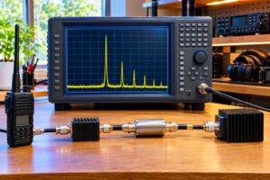
Never connect a transmitter directly to an SDR input. A 5-watt HT is about 37 dBm. If your SDR input is safe only around 0 dBm or below, direct connection can destroy it immediately. With 60 dB of attenuation, that 5-watt signal becomes about -23 dBm before cable and sampler losses, a much safer level. A 50-watt transmitter is about 47 dBm, so the same 60 dB chain produces about -13 dBm. Always calculate first, then add a safety margin.

A Step-by-Step Amateur Radio Spurious Emissions Test

1. Confirm the Test Path Before Transmitting

Connect the transmitter to the dummy load through the intended sampler or attenuator chain. Verify that the dummy load is attached, not the antenna. Check connector tightness, power ratings, and the maximum input rating of the spectrum analyzer or SDR.

If using an SDR, start with extra attenuation and low gain. SDR overload can create false signals that look like transmitter spurs. When in doubt, reduce gain and add attenuation; real transmitter emissions will track with transmitter power, while many overload artifacts change unpredictably with receiver gain.

2. Measure the Fundamental Safely

Transmit at low power first. Tune the analyzer or SDR to the fundamental frequency and confirm that the displayed signal is stable and not clipping the instrument. Note the displayed level and the total attenuation or coupling factor in the measurement path.

You do not always need absolute transmitter power to perform a relative dBc check. If the same measurement path is used, the difference between the fundamental and the harmonic is what matters. However, frequency response matters. Attenuators, couplers, cables, filters, and SDR front ends may not be flat from HF through UHF.

3. Scan Harmonic Frequencies

Calculate at least the second and third harmonics. For example, if testing at 14.250 MHz, check near 28.500 MHz and 42.750 MHz. If testing a 146.520 MHz handheld, the second harmonic is near 293.040 MHz and the third harmonic is near 439.560 MHz, which is especially important because it can land in another amateur band or near sensitive services depending on the transmit frequency.

At each harmonic, use a suitable span and resolution bandwidth. A narrower resolution bandwidth lowers the displayed noise floor but takes longer to sweep. Keep settings consistent when comparing levels, or record the settings carefully.

4. Apply Corrections

If you change attenuation between the fundamental and harmonic measurements, correct the reading. Example: the fundamental is measured at -20 dBm with 60 dB of attenuation. The second harmonic is measured at -72 dBm with 40 dB of attenuation. Because the harmonic measurement used 20 dB less attenuation, its comparable level would be -92 dBm relative to the original path. The difference is 72 dB, so the second harmonic is approximately -72 dBc, before accounting for frequency-response errors.

That example is simplified. A directional coupler may have different coupling loss at HF, VHF, and UHF. An SDR may show a sloped response. If the result is close to the legal limit, treat it as inconclusive unless you can verify the measurement chain.

5. Look for Non-Harmonic Spurs

After harmonic checks, scan a wider range around the operating frequency and across likely problem areas. Kit transmitters and modified radios may leak clock oscillators or synthesizer products. Amplifiers can oscillate outside the intended band. Switch-mode power supplies can add hash that rides on the transmitted signal.

A useful clue is repeatability. A real spur should appear when the transmitter is keyed into the dummy load and disappear when unkeyed. It should increase or decrease consistently with RF output power. If it stays present with the transmitter off, you may be seeing local RF, computer noise, or an SDR artifact.

Special Notes for HTs, Kits, and Amplifiers

Handheld Transceivers

HT testing is tricky because many handhelds use an antenna connector and chassis design that assumes a compact antenna, not a bench full of adapters. Use a proper adapter, keep the path short, and avoid stressing the connector. Test on low power first. Some low-cost radios have had public concern over harmonic performance, so checking the second and third harmonics is worthwhile before relying on one near repeaters, public-service events, or shared sites.

Homebrew and Kit Radios

For kits, test before final enclosure assembly and again after the radio is boxed. Shielding, grounding, output-filter layout, and connector bonding can change results. If a harmonic is high, inspect the low-pass filter values, solder joints, toroid winding count, relay routing, and ground return paths. A tiny construction error in an output filter can make a large difference.

External RF Amplifiers

Amplifiers should be tested at realistic drive levels into a dummy load. Overdriving an amplifier can create harmonics, intermodulation, and broadband garbage even if the exciter is clean. Verify band switching, output filtering, bias, and load match. A clean exciter does not guarantee a clean amplified signal.

Common Measurement Traps

  • Instrument overload: The analyzer or SDR creates false harmonics because the fundamental is too strong.
  • Radiating test leads: Poor shielding or loose adapters let RF leak into the receiver input by unintended paths.
  • Wrong dummy load: Some loads are fine at HF but poor at UHF, where mismatch can distort results.
  • Ignoring duty cycle: Digital modes, FM, and key-down tests can overheat loads and attenuators quickly.
  • Assuming SDR accuracy: Many SDRs are excellent learning tools but need calibration and cautious gain settings for measurement work.
  • Forgetting occupied bandwidth: A harmonic check does not prove that SSB audio, AFSK, FT8, FM deviation, or CW keying is clean.

What to Do If You Find a Problem

First, confirm that the signal is real. Add attenuation, reduce SDR gain, change cables, and repeat. If the spur tracks transmitter power and appears at the expected frequency, investigate the transmitter rather than trying to explain it away.

For high harmonics, inspect or add appropriate low-pass filtering. For VHF/UHF HT issues, the practical answer may be using a better-filtered radio or an external filter designed for the band and power. For amplifier problems, reduce drive, check tuning, verify band selection, and confirm that the load is actually 50 ohms at the operating frequency. For broadband noise, test with a different power supply and remove nearby digital devices from the setup.

If interference has already been reported, stop transmitting on the suspect setup until the cause is identified. The ARRL maintains general regulatory and RFI information that can help operators think through interference responsibilities and resolution steps.

Preflight Checklist

  • Use a dummy load rated for the power, frequency, and duty cycle.
  • Calculate transmitter power in dBm and choose enough attenuation before keying.
  • Start at low power and verify the analyzer or SDR is not overloaded.
  • Measure the fundamental and record settings.
  • Check at least the second and third harmonics; check more if practical.
  • Correct readings for changed attenuation, coupling loss, and known frequency response.
  • Scan for non-harmonic spurs and broadband noise.
  • Repeat after adding an amplifier, changing filters, or moving from bench wiring to the final enclosure.
  • Do not connect the radio to an antenna until obvious problems are resolved.

Helpful References

For the legal baseline, read 47 CFR §97.307. For the enforcement context, see ARRL’s report, FCC Warns Licensee on Out-of-Band Transmissions. For practical interference background, ARRL’s Regulatory RFI Information page is also useful. ARRL’s technical article archive includes measurement and interference material, including a QST technical PDF on RF interference topics.

FAQs

Can an SDR replace a spectrum analyzer?

An SDR can be useful for screening, especially when paired with good attenuation and careful gain control. However, many SDRs have limited dynamic range, uncertain amplitude accuracy, and overload behavior that can mimic spurs. Treat close results as a reason for better measurement, not as a final compliance determination.

Should I test into an antenna?

No. Use a dummy load for preflight measurements. Testing into an antenna can radiate the very spurious emissions you are trying to evaluate and can expose the measurement to propagation, local signals, and pickup errors.

How low should harmonics be?

Check the current Part 97 requirement for your frequency and power level. As a practical station goal, leave margin below the applicable limit because hobby-grade measurement uncertainty can easily be several dB or more.

Does a low SWR mean the signal is clean?

No. SWR only describes how the load impedance relates to the transmitter system at the measured frequency. A transmitter can show a good SWR and still produce harmonics, spurs, splatter, or broadband noise.

Key Takeaways

  • An amateur radio spurious emissions test is a practical bench habit for HTs, kits, amplifiers, and modified gear.
  • Use a dummy load, adequate attenuation, and a measurement device that is protected from overload.
  • Measure harmonics by comparing them with the fundamental in dBc, while accounting for changed attenuation and frequency response.
  • Part 97 sets the regulatory baseline, but clean operation also requires attention to drive level, filtering, shielding, grounding, and occupied bandwidth.
  • If a spur is real and repeatable, fix the station before connecting an antenna.
Posted on — Leave a comment

ASL3 Repeater Node Tune-Up: Debian 13, Allmon3, Audio Levels, and Safe Updates

Why an ASL3 tune-up deserves a plan

An AllStarLink ASL3 repeater setup is not just a Linux computer with a sound interface. On a club machine, it is part of a working VHF or UHF repeater system with real users, scheduled nets, control responsibilities, coordinated frequencies, and expectations that the link will behave predictably. A casual upgrade can break audio, change firewall behavior, disable a web dashboard, or leave the repeater connected when it should not be.

The current AllStarLink documentation emphasizes ASL3 on Debian 13 and Debian 12, with installation and updates handled through Debian-style packages. That is good news for maintainability, but it also means repeater owners should think like system maintainers: document the existing node, back up configuration files, test off-air where possible, and schedule changes outside heavy-use periods.

This guide focuses on practical tune-up work for an existing or new ASL3 repeater node: choosing a Debian base, keeping Allmon3 useful and secure, checking audio levels, and applying updates without surprising the club.

Start with a written node baseline

Before installing or upgrading anything, capture the current state. This is especially important if the node was built years ago and only one operator remembers how it works. A useful baseline does not need to be fancy. It should let another licensed control operator restore service or make an informed decision during a failure.

  • Node number and purpose: repeater full-time link, private hub, portable backup, event link, or test node.
  • Radio interface: URI, CM108/CM119-based interface, repeater controller port, direct discriminator audio, speaker audio, COS, CTCSS, and PTT wiring.
  • Repeater details: band, output/input pair, CTCSS or DCS use, wide or narrow deviation expectation, and coordination constraints.
  • Network details: static IP or DHCP reservation, firewall rules, router port forwards if used, and remote access method.
  • Software files changed locally: ASL configuration files, Allmon3 configuration, scripts, cron jobs, firewall rules, and any custom audio settings.
  • Rollback path: image backup, spare storage card or SSD, spare node computer, or a known-good previous configuration archive.

For a club repeater, also record who is authorized to make linking changes and who can approve downtime. That is a governance issue, but it prevents technical fixes from becoming on-air confusion.

Debian 13 or Debian 12: choose stability over novelty

The AllStarLink installation documentation currently points operators toward ASL3 on Debian 13 or Debian 12. Both can be reasonable choices, but the best answer depends on your maintenance style and hardware support. Debian 13 may be attractive for newer hardware and a longer forward-looking platform. Debian 12 may be preferred when a club wants a conservative base that has already been widely used in server environments.

For a repeater node, the operating system decision should be made around reliability, not excitement. Check that your computer, USB radio interface, network adapter, storage device, and any remote-management hardware work cleanly with the Debian version you plan to use. If you are using an older mini PC, single-board computer, or recycled desktop, verify boot behavior after power loss. A repeater site that requires a long drive or tower-crew coordination is the wrong place to discover that the machine stops at a keyboard prompt.

Practical Debian installation habits

  • Use a clean installation for major platform changes when possible, rather than dragging years of unknown package state forward.
  • Prefer wired Ethernet at fixed sites. Wi-Fi can work, but it adds another failure mode and may be unreliable in RF-dense environments.
  • Use a DHCP reservation or static network plan that is documented in the site notes.
  • Disable unnecessary services. A repeater node should be simple enough to understand under pressure.
  • Keep local console access possible. Remote access is convenient; local recovery is what saves a bad update.

Follow the official AllStarLink Debian installation instructions for the current package names and repository steps. Do not rely on copied commands from old forum posts unless they match the current documentation for ASL3.

Install ASL3 like a service, not a science project

ASL3 benefits from package-based installation and updates, but the repeater owner still has to make site-specific decisions. The node number, registration details, radio interface type, COS polarity, PTT logic, DTMF behavior, hang time, courtesy tone behavior, and link control policies are all operational choices.

A practical approach is to build the node in three stages:

  • Bench stage: install Debian and ASL3, confirm the node boots, verify the USB interface is detected, and confirm ASL services start properly.
  • Dummy-load or low-risk RF stage: connect a test radio or service monitor path, check PTT, COS, DTMF decoding, and basic audio without touching the production repeater.
  • Repeater integration stage: connect to the controller or repeater interface during a scheduled maintenance window and test with a control operator monitoring.

Do not skip the bench stage. Many apparent AllStar problems are actually USB enumeration, audio-device selection, cable wiring, COS polarity, or Linux network problems. Separating those from repeater integration saves time.

Allmon3: useful management without risky exposure

Allmon3 is the current web-based monitoring and control tool documented by AllStarLink for ASL3 systems. It can be extremely helpful for seeing node status, connected nodes, and common control actions. It is also a management surface, so it should be treated with the same caution as any administrative web tool.

Install and configure Allmon3 using the official AllStarLink Allmon3 installation documentation. Avoid assuming that settings from older Allmon versions will transfer directly without review. After installation, confirm these points:

  • Authentication: use strong credentials and do not share one account casually among all club members.
  • Access scope: decide whether Allmon3 should be LAN-only, VPN-only, or reachable through a carefully secured remote-access path.
  • Node display: verify the correct node or nodes appear, especially if the server hosts more than one node.
  • Control behavior: test connect and disconnect actions during a maintenance window, not during a net.
  • Logging: know where to look when Allmon3 does not show what operators expect.

For many clubs, the safest pattern is remote access through a VPN or other authenticated private path rather than exposing management pages directly to the public internet. If web exposure is necessary, use current TLS practices, strong authentication, and a firewall policy that reflects the actual need. Do not confuse convenience with control security.

Audio levels: the part everyone hears

Audio alignment is where a technically successful node becomes a pleasant or unpleasant repeater experience. Users rarely know whether Debian packages are current, but they immediately notice low transmit audio, clipped syllables, harsh levels, excessive courtesy-tone volume, or a link that overdrives the repeater.

The goal is not “as loud as possible.” The goal is clean, consistent deviation and intelligible audio that matches the repeater’s normal local audio. For VHF and UHF FM repeaters in the United States, exact deviation targets depend on system design, channel spacing, coordination, and local practice. A traditional wideband amateur FM system is commonly aligned around a 5 kHz maximum-deviation environment, while some systems operate narrower. Follow your repeater’s design and coordination expectations.

Receive audio into ASL3

Receive audio is the audio your node hears from the repeater receiver or controller. If it is too low, DTMF decoding and linked audio may be weak. If it is too high, speech can clip before it ever reaches the network.

  • Prefer a stable, flat audio source when available, such as discriminator or dedicated receiver audio specified by the repeater/controller documentation.
  • If using speaker audio, remember that volume-control changes can disturb the node alignment.
  • Confirm COS or carrier-detect behavior separately from audio level. A clean signal path is not useful if the node keys and unkeys incorrectly.
  • Use a service monitor, calibrated test set, or known alignment procedure when available. By-ear adjustment is a last resort, not a standard.

Transmit audio from ASL3 to the repeater

Transmit audio is what your node sends into the repeater transmitter path or controller. It should match local microphone audio in loudness and quality without splatter, clipping, or overemphasized tones. If the repeater controller also generates courtesy tones, IDs, or local announcements, check that linked audio does not mask them or create confusing level differences.

  • Set ASL3 transmit audio with the repeater connected to proper test equipment when possible.
  • Check both voice and DTMF behavior if DTMF commands are used on the RF side.
  • Verify CTCSS or DCS handling. Tone levels should be appropriate for the system and not excessive.
  • Test a linked QSO path with a control operator listening locally and, if possible, a second operator listening through the link.

Never increase levels to compensate for a bad cable, noisy interface, or incorrect audio tap. Fix the underlying problem first.

Safe update workflow for a club repeater node

The AllStarLink user guide describes package-based updates for ASL3 systems. That is the correct maintenance direction: use the distribution package tools and the project’s documented update path. The operational question is when and how to update.

A safe update process looks like this:

  • Read first: check the official update guidance and any relevant release notes before touching the production node.
  • Back up: copy ASL configuration, Allmon3 configuration, custom scripts, network settings, and any locally edited files. For small systems, a full disk image before major work is often worth the time.
  • Schedule: avoid nets, severe-weather watch periods, public-service events, and times when the repeater is heavily used.
  • Notify: tell club control operators what will change, when, and how long the node may be unavailable.
  • Update packages: use the documented Debian package workflow rather than manual file replacement.
  • Reboot if needed: do not assume a service restart proves the machine will survive a power cycle.
  • Verify: check registration, linking, audio, Allmon3 display, logs, and local RF behavior.
  • Record: update the node baseline with package date, Debian version, ASL3 version information where available, and any configuration changes.

The most important habit is to separate package updates from experimental configuration changes. If you update the system, change audio wiring, alter firewall rules, and modify node commands all in the same evening, troubleshooting becomes much harder.

Staging node: cheap insurance for linked repeaters

If your club depends on AllStarLink for regular nets or regional coverage, consider keeping a staging node. It does not need to be connected to the main repeater. A modest computer, spare USB interface, and dummy-load radio path can reveal many issues before the production node is touched.

A staging node is useful for confirming that Debian updates install cleanly, Allmon3 behaves as expected, USB audio devices retain their identity, and configuration syntax remains valid. It also gives new technical volunteers a place to learn without risking the main repeater.

For best results, make the staging node similar to production where it matters: same Debian generation, same ASL3 package source, same radio-interface family, and similar network assumptions. It does not have to be identical, but it should be close enough to catch the problems you actually fear.

Troubleshooting symptoms after an upgrade

Node boots but does not link

Check basic network connectivity first, then verify ASL services are running and the node is configured with the expected identity. Look for DNS, firewall, routing, or registration problems before editing audio files. A linking failure is often not an RF problem.

Allmon3 loads but shows the wrong status

Confirm Allmon3 is pointed at the correct local node and that its access to the ASL management interface is configured as documented. If the server hosts multiple nodes, make sure you are viewing the intended one.

Repeater keys unexpectedly

Disconnect the transmitter control path if necessary to protect the repeater. Then inspect PTT polarity, COS logic, USB interface mapping, and any scripts or startup macros. A stuck PTT condition is operationally serious and should not be debugged casually on the live transmitter.

Audio is distorted after updates

Check whether the selected audio device changed, mixer settings changed, or the interface was enumerated differently. Then repeat the receive and transmit level checks. Do not assume the software update changed the audio path; USB device ordering and mixer state can create similar symptoms.

Safety and regulatory reminders

AllStarLink does not remove normal amateur-radio responsibilities. The station still needs appropriate licensing, control, identification, RF exposure compliance, and operation within applicable rules. In the United States, consult current FCC Part 97 requirements and your repeater coordination practices. International operators should follow their own regulator’s rules.

At repeater sites, also respect electrical and physical safety. Use proper grounding and surge protection practices, avoid unsafe tower or rooftop work, protect power wiring with appropriate fusing, and do not work alone in hazardous locations. If the node is connected to emergency power, understand battery and DC distribution risks before making changes.

Key takeaways

  • A reliable AllStarLink ASL3 repeater setup starts with documentation, backups, and a rollback plan.
  • Use the official ASL3 Debian installation and update documentation rather than stale copied commands.
  • Allmon3 is valuable, but it should be authenticated and exposed only as much as necessary.
  • Audio alignment should be measured and matched to the repeater system, not adjusted for maximum loudness.
  • Package updates are safest when staged, scheduled, verified, and recorded.

FAQ

Should a club repeater node move to ASL3 immediately?

Not automatically. If the current node is stable, plan the move rather than rushing it. Build or image a replacement, test the radio interface, confirm Allmon3 access, and schedule the cutover. ASL3 is the current direction, but good timing matters.

Can I tune ASL3 audio by listening on a handheld?

A handheld can reveal obvious distortion or low audio, but it is not a substitute for proper deviation measurement. Use a service monitor or calibrated test method whenever possible, especially on a repeater transmitter.

Is it safe to run updates remotely?

It can be, but only if you have a recovery path. Remote updates are risky when the site is difficult to access, the node has no out-of-band management, or the club cannot tolerate extended downtime. Major changes deserve local access or a known rollback method.

Should Allmon3 be public on the internet?

Usually, a private access method such as VPN is safer. If public access is used, protect it with strong authentication, current web security practices, and restrictive firewall rules. Treat it as a control interface, not just a status page.

Sources

Posted on — Leave a comment

Leonids 2026 Meteor Scatter: Your 6m and 10m MSK144 Plan for the Nov. 17 Peak

Why the 2026 Leonids Matter for MSK144 Operators

Leonids 2026 meteor scatter MSK144 operating is worth planning early because the shower gives VHF and upper-HF operators a predictable window to sharpen timing, station setup, and exchange discipline. The International Meteor Organization’s meteor shower calendar lists the Leonids as a recurring November shower, and NASA describes the Leonids as fast meteors associated with comet 55P/Tempel-Tuttle. For radio amateurs, the practical takeaway is simple: more ionized meteor trails can mean more opportunities for brief, decodable pings on bands such as 50 MHz and, when conditions cooperate, 28 MHz.

Do not read that as a guarantee. Meteor scatter is statistical, not scheduled. A shower peak improves the odds of useful bursts, but antenna direction, local noise, time of day, station capability, operator discipline, and the actual shower behavior all matter. The goal is to have your station ready before Nov. 17, 2026, so you are not troubleshooting audio levels, clock sync, or message sequencing while the better activity is already underway.

HamSCI has promoted MSK144 activity around 6 meters and 10 meters as a citizen-science-friendly operating opportunity. That makes 2026 a good year to combine ordinary amateur operating with careful logging of time, band, grid, and decode behavior. Even if you do not submit data anywhere, disciplined station notes will make you a better meteor scatter operator.

What MSK144 Is Doing That SSB and CW Cannot

MSK144 is one of the digital modes in WSJT-X designed for brief meteor-scatter bursts. Meteor trails may support a path for fractions of a second to several seconds. Human-speed exchanges are often too slow for the shortest pings, while MSK144 uses structured messages, tight timing, and fast decoding to complete contacts during short openings.

On 6 meters, MSK144 is widely used for meteor scatter because 50 MHz is high enough to benefit from ionized trails yet low enough that modest stations can participate. On 10 meters, meteor scatter can also occur, and the larger amateur population with 28 MHz-capable equipment makes it attractive for coordinated activity. Propagation on 10 meters can also include sporadic E, F-layer, and other mechanisms, so log honestly: a completed MSK144 QSO during the Leonids is not automatically proof that every decode came by meteor scatter.

Pick the Right Operating Windows Around Nov. 17

For U.S. operators, plan in UTC and local time. The Leonids are generally a mid-November shower, with peak timing published by meteor organizations closer to the event. Check the current IMO calendar before the operating weekend and convert the listed peak time into your local time zone.

As a practical plan, keep three windows open:

  • Pre-peak shakedown: One or two evenings before Nov. 17, verify WSJT-X, rig control, audio, PTT, antenna switching, and logging.
  • Peak window: Operate across the hours around the predicted maximum, especially when the Leonid radiant is favorably placed for your location.
  • Post-peak follow-up: Continue into the following morning or evening. Meteor activity does not stop sharply at the published peak.

For many northern-hemisphere operators, meteor scatter activity is often productive in the pre-dawn hours because the observing location is moving into the meteoroid stream. With the Leonids, the radiant in Leo rises late and is better placed later in the night. Still, do not ignore evenings: random meteors, long-path geometry, and coordinated schedules can produce contacts outside the textbook “best” hours.

6 Meters vs. 10 Meters: How to Choose Your Band

6 meters: the primary MSK144 band

If you have a 50 MHz-capable transceiver, reasonable feed line, and even a small directional antenna, make 6 meters your main Leonids MSK144 band. A three- to five-element Yagi at modest height can be very effective, but loops, Moxons, and other horizontal antennas can participate. Keep expectations realistic: antenna pattern, takeoff angle, local noise, and path geometry all influence results.

Use current band plans and event guidance to select operating frequencies. Do not assume that a frequency mentioned in an old article is still appropriate or clear. Before transmitting, listen or decode, check for local usage, and follow your license privileges.

10 meters: useful, but interpret carefully

On 10 meters, MSK144 can be productive during meteor activity, especially when operators coordinate times and calling areas. However, 28 MHz is also a band where other propagation modes may appear. If you see long, steady decodes or broad regional openings, you may be working a mix of mechanisms rather than pure meteor scatter.

Technician, General, Amateur Extra, and other license classes have different privileges on 10 meters. U.S. operators should verify the current FCC rules for data emissions and frequency segments before operating. International operators should check their national allocation and band plan.

WSJT-X Setup Checklist for MSK144

Install a current stable version of WSJT-X from the official project site, then configure it before the shower. Avoid making first-time changes during peak activity.

  • Enter your call sign and grid square. A correct four-character grid is essential for standard MSK144 exchanges.
  • Set the mode to MSK144. Confirm the waterfall, message panel, and decoding controls change accordingly.
  • Use accurate computer time. Enable a reliable time-sync method so your clock stays within a small fraction of a second if possible. Poor timing causes missed decodes and broken sequences.
  • Confirm CAT control or manual frequency discipline. Your radio and WSJT-X must agree on band, mode, and audio path.
  • Use USB or data mode as appropriate for your radio. Follow your transceiver manual for digital audio operation.
  • Set transmit audio conservatively. Avoid ALC action, overdriven audio, RF speech processing, compression, and equalization intended for voice.
  • Enable standard messages and auto-sequencing only after you understand the flow. Auto-sequence is helpful, but you remain responsible for transmitting correctly.
  • Log UTC, band, frequency, grid, and notes. Include whether the QSO appeared burst-like, sustained, or mixed with other propagation.

Use 15-second transmit/receive periods unless current event instructions specify otherwise. Coordinate “first” or “second” sequence when scheduling. If both stations transmit in the same period, neither station will copy the other. For random calling, follow normal regional practice and watch how active stations are sequencing before joining.

Clean Transmit Audio and Duty Cycle Matter

MSK144 is not a casual microphone mode. Your transmitter should produce a clean digital signal without splatter or distortion. Set the radio for the proper digital input, reduce computer output, and increase drive only to the point needed for the intended RF power. If the ALC meter moves heavily, back down. Turn off speech processing. Keep equalizers flat or disabled.

Digital meteor scatter can involve repeated 15-second transmissions. That is a demanding duty cycle for some radios, amplifiers, power supplies, and antennas. Verify that your equipment is rated for the power level and mode. A conservative, clean 50 watts is usually better than a distorted high-power signal that creates interference and overheats gear.

Antenna Direction and Practical Station Strategy

For scheduled QSOs, point toward the other station or toward the expected common reflection region along the path. For random calling on 6 meters, many operators aim toward population centers or likely activity areas rather than constantly turning the antenna. If you have a rotator, move deliberately; if you have a fixed antenna, pick a useful broad coverage direction and operate patiently.

Horizontal polarization is common for weak-signal VHF work in North America, including 6-meter meteor scatter. On 10 meters, many stations use whatever efficient antenna they already have. Vertical antennas may work, but polarization differences and local noise can matter. The best antenna is the one that is resonant, safe, reasonably efficient, and available when the shower arrives.

Standard MSK144 Exchange Example

A typical WSJT-X-style meteor scatter exchange uses call signs, grid squares, signal reports, acknowledgments, and 73. Exact formatting depends on the software and current operating practice, but the logic is usually:

  • CQ message: CQ K1ABC FN42
  • Reply: K1ABC W9XYZ EN52
  • Report: W9XYZ K1ABC +03
  • Roger report: K1ABC W9XYZ R+02
  • Confirmation: W9XYZ K1ABC RRR
  • Closing: K1ABC W9XYZ 73

Do not improvise long free-text messages during weak meteor scatter conditions. The structured messages exist because bursts are short. If you are participating in a special activity, follow its exchange instructions. If the activity asks for grid squares, do not substitute a state abbreviation unless that is explicitly part of the exchange.

Logging for Operating Value and Possible Science Value

Good logs are useful even when no formal reporting is required. Record the UTC date and time, band, frequency, worked station, grid, sequence, signal reports, and antenna direction. Add short notes such as “short pings only,” “several long bursts,” “possible Es,” or “sustained decode.” These notes help separate meteor-scatter behavior from other propagation later.

If HamSCI or another group provides a reporting format for the 2026 activity, follow that format rather than inventing your own. Citizen-science value depends on consistent timekeeping, location data, and honest reporting. Do not “clean up” logs to make them look more impressive.

Troubleshooting Before the Shower Peak

  • No decodes: Check time sync, audio input device, receiver mode, squelch settings, and whether the band is actually active.
  • Others decode you poorly: Reduce transmit audio, check ALC, verify frequency, and confirm your clock.
  • Rig does not transmit: Test CAT/PTT settings, data mode selection, audio routing, and interface cabling.
  • RF gets into the computer: Add ferrites, improve station grounding/bonding, reduce power, and separate RF cables from USB and audio leads.
  • High SWR: Stop and fix the antenna or feed line. Do not use the shower peak as a reason to abuse equipment.

Safety and Regulatory Caveats

Follow your license privileges, national regulations, and current band plans. In the United States, also consider RF exposure compliance, especially on 6 meters and 10 meters with directional antennas or amplifiers. Keep people away from active antennas, use proper mast hardware, avoid overhead power lines, and disconnect outdoor antennas during lightning risk. Portable operators should secure masts, manage batteries safely, and avoid operating in unsafe weather just to chase a peak hour.

Key Takeaways

  • Check the current IMO calendar for the 2026 Leonids peak timing and convert it to local time.
  • Use 6 meters as the main MSK144 meteor scatter band if your station supports it; add 10 meters if you can operate legally and cleanly.
  • Configure WSJT-X, clock sync, audio levels, PTT, logging, and antenna switching before Nov. 17.
  • Use short, standard exchanges and disciplined 15-second sequencing.
  • Log honestly, including notes about possible non-meteor propagation.

FAQ

Do I need a large 6-meter Yagi for the Leonids?

No. A directional antenna helps, but many operators start with modest antennas. A clean station, accurate timing, and good operating habits often matter more than maximum gain.

Can I use FT8 instead of MSK144?

FT8 may make contacts on 6 or 10 meters when propagation supports it, but MSK144 is specifically designed for fast meteor-scatter bursts. For Leonids meteor scatter activity, MSK144 is the more appropriate choice.

Is every 10-meter MSK144 contact during the Leonids meteor scatter?

Not necessarily. Ten meters can support several propagation modes. Use burst behavior, timing, path, and band conditions as clues, but avoid overclaiming certainty.

Where should I verify dates and software details?

Use current primary sources before the event: the International Meteor Organization meteor shower calendar, NASA’s Leonids overview, the official WSJT-X page, and HamSCI’s MSK144 activity guidance.

Posted on — Leave a comment

POTA ADIF Preflight in 2026: Use Browser Validation to Catch Bad Modes, Parks, and Duplicate Files

Why POTA ADIF Validation Matters After the Activation

For many Parks on the Air activators, the radio work is the fun part: finding a quiet operating spot, getting an antenna in the air, handling pileups, and making contacts before weather, batteries, or park hours close the window. The less glamorous part is log cleanup. But that last step determines how quickly hunters receive credit and whether you spend the next day answering fix-it messages.

In 2026, the rebuilt POTA.app made that cleanup easier. The official POTA.app changelog notes October 2026 improvements including per-QSO browser validation, duplicate-file checks, and ADIF-mode updates. In plain English, the uploader is getting better at warning you about problems before a bad log becomes someone else’s missing credit.

POTA ADIF validation is not just a software feature. It is a practical preflight habit: verify that the file describes the correct station, park, date, time, band, mode, and park-to-park information before you submit it. When you also operate SOTA from the same summit or park, that habit becomes even more important because one contact may need to satisfy two different award systems with different log requirements.

The Three Upload Problems Activators Can Prevent

1. Bad or Nonstandard Modes

Mode errors are common because logging programs, digital-mode applications, contest loggers, and hand-edited ADIF files do not always express modes the same way. A voice QSO on 20 meters might be straightforward as SSB, but digital contacts can be more complicated because ADIF supports modes and submodes. Some programs export modern digital contacts cleanly; others may create free-text values that look obvious to a human but are not valid ADIF for automated processing.

The October 2026 POTA.app ADIF-mode updates are useful because the validator can compare your file against the current accepted handling in the site rather than relying on your memory. Do not try to outsmart the validator by inventing simplified names such as DIGITAL, DATA, or FT-MODE. Export from a current logger, preserve the logger’s ADIF fields unless you know exactly what you are changing, and let the browser validation point out fields that need attention.

2. Wrong Park References

A wrong park reference can happen in several ways. You might log yesterday’s park because your logger profile did not change. You might type one digit wrong in a park-to-park note. You might activate multiple references and include only one. Or you might copy an old reference from a personal spreadsheet that has not been checked against current POTA data.

The official POTA ADIF reference explains how POTA-related fields are represented in ADIF. In general, activators should pay close attention to the fields that identify the station, the operator when applicable, the activated park reference, and any hunted park reference for park-to-park credit. The important point is not to memorize every tag name; it is to make sure your exported file actually says what happened on the air.

3. Duplicate Files

Duplicate uploads are easy to create after portable operations. You may export once from your laptop, again from your phone, and again after adding a missing QSO. If the file name changes, it may not be obvious which version was already submitted. Duplicate-file checks in the browser help protect you from resubmitting the same activation file and creating avoidable confusion.

A duplicate-file warning does not mean you should ignore real corrections. If you discovered a missing contact, a wrong mode, or a park-to-park field that needs repair, prepare a clean corrected export according to current POTA guidance. The duplicate warning is a signal to slow down and confirm whether you are replacing, correcting, or accidentally repeating the same data.

A Practical POTA ADIF Preflight Workflow

Use this workflow after every activation, especially when you operated from more than one park, used more than one radio, or logged on more than one device.

Step 1: Preserve the Raw Log

Before editing anything, save the original log from your logger or paper notes. If you used a field notebook, photograph the pages before packing away. If you logged on a laptop, keep the native log file as well as the exported ADIF. This gives you a fallback if an edit goes wrong.

Step 2: Confirm the Activation Identity

Check the call sign used on the air, the operator if different, the UTC date, and the activated park reference. POTA logging is based on UTC, not local time. An evening activation in the United States can cross into the next UTC date, which can surprise activators who name files by local calendar date. If you worked from 7:30 p.m. to 9:15 p.m. Central Time, part or all of that operation may fall on the next UTC day depending on daylight saving time and the season.

For POTA, use the current guidance in POTA’s submitting logs documentation. Do not rely solely on an old club handout, a saved checklist from several years ago, or another operator’s file name convention if the official instructions have changed.

Step 3: Scan the Core QSO Fields

Every QSO should have a contacted call sign, date, time, band or frequency information, and mode. Look for obvious field errors: missing times, local-time entries, impossible bands for your actual setup, or copied call signs that contain spaces or punctuation. If your logger records frequency, make sure it matches the band you used. If it records only band, verify that the band is correct.

A simple example: suppose you activated a US park on 20 meters SSB, then switched to 40 meters CW. If your entire ADIF export says 20M SSB, the file may upload but it does not accurately describe the contacts. Browser validation can catch many structural problems, but it cannot always know what antenna switch you moved or what band you actually used.

Step 4: Review Modes Before Upload

Sort or filter the log by mode. Confirm that voice, CW, and digital contacts appear as real ADIF-compatible mode values rather than notes. Be especially careful when importing QSOs from WSJT-X, JS8Call, fldigi, N1MM Logger+, HamRS, or another logger into a second application. Import-export chains are where mode fields can be altered unintentionally.

If POTA.app flags a mode, do not randomly rename it. First update your logging software if needed, then re-export. If you must edit the ADIF directly, make a copy and change only the specific field you understand. ADIF tags include field lengths, so careless manual editing can corrupt the file if the length indicator no longer matches the value.

Step 5: Validate Park-to-Park Contacts

Park-to-park contacts are valuable to both sides, but they require accurate park information. If you contacted another activator, record the other activator’s park reference in the correct POTA field rather than burying it only in a comment. The official POTA park-to-park documentation is the right reference for current handling.

During a pileup, it is easy to mishear a reference. If the other operator says K-1234 and your log says K-1324, the call sign may be correct but the park-to-park credit can fail or require cleanup. Good field practice is to repeat the park reference back when conditions allow, especially on noisy HF paths.

Step 6: Use Browser Validation Before Final Submission

When you upload through the current POTA.app interface, pay attention to the per-QSO validation feedback. Per-QSO checking is especially helpful because it points to the individual contact that needs review rather than leaving you to search the whole file. Treat warnings as a preflight checklist, not as a nuisance.

If the validator reports a duplicate file, stop and compare the file against your submitted records. Confirm the park, date, QSO count, and whether the file contains corrections. If you are unsure, avoid repeated uploads and consult the current POTA help path rather than creating multiple conflicting attempts.

Joint POTA and SOTA Activations

Many portable operators enjoy combining POTA and Summits on the Air when a summit, trailhead, or nearby public land makes it practical. The logging principle is simple: keep one accurate source record of what happened, then export or enter data according to each program’s requirements.

Do not assume a POTA-ready ADIF file is automatically a SOTA-ready submission, or the other way around. POTA focuses on park references and its own ADIF handling. SOTA has its own summit references, chaser and activator processes, and database expectations. For joint activations, record both references in the field, but submit each program’s log in the format and workflow that program currently requires.

Field Habits That Make Validation Easier

  • Set your logger profile before calling CQ. Confirm call sign, park reference, UTC clock, and default mode.
  • Log UTC, not local time. Sync the device clock before leaving home if you will be offline.
  • Announce and confirm park-to-park references. Repeat the other reference when conditions permit.
  • Keep notes for band and mode changes. A short paper note such as 1812Z changed to 40 CW can solve later confusion.
  • Export once, review once, then upload. Avoid multiple nearly identical ADIF files scattered across devices.
  • Do not hand-edit the only copy. Keep an untouched original and edit a duplicate if correction is necessary.

Safety and Regulatory Notes for Portable Operators

Clean logs matter, but safety and legal operation come first. Operate only within your license privileges, follow current FCC rules in the United States, and respect band plans and local restrictions. Portable antennas, masts, counterpoise wires, and batteries introduce real hazards. Keep antennas away from power lines, manage trip hazards around public trails, protect lithium batteries from damage and overheating, and evaluate RF exposure for your operating setup. Park rules, weather, terrain, and shared public access may limit where and how you can operate.

FAQ

Does browser validation guarantee my POTA log is perfect?

No. Validation can catch many format, mode, park, and duplicate-file issues, but it cannot know everything that happened in the field. You are still responsible for accurate call signs, times, bands, modes, and references.

Should I edit ADIF files by hand?

Only when necessary and only on a copy. ADIF is readable, but its tagged field lengths make careless edits risky. Whenever possible, fix the data in your logging program and export a fresh file.

What if my digital mode is flagged?

Check whether your logger is current and whether the export uses accepted ADIF mode or submode handling. Avoid inventing a replacement value. Re-export from updated software when practical, then validate again.

How should I handle a corrected upload?

Follow the current POTA submission guidance. Keep records of the original file, the corrected file, and what changed. If the site warns that the file is a duplicate, verify whether you are truly submitting a corrected version or accidentally repeating the same upload.

Key Takeaways

  • POTA ADIF validation is a final preflight step that helps hunters receive credit faster and reduces avoidable cleanup.
  • Mode names, park references, UTC dates, and park-to-park fields deserve special attention.
  • The 2026 POTA.app browser improvements make per-QSO problems easier to find before submission.
  • Duplicate-file warnings are useful prompts to compare versions before uploading again.
  • For joint POTA and SOTA activations, maintain one accurate source log but submit according to each program’s current rules.
Posted on — Leave a comment

Stop Losing New Satellites: Move Your Tracker from Legacy TLEs to GP/OMM Feeds

Why This Matters Now

For years, amateur satellite operators have treated Two-Line Element sets, usually called TLEs, as invisible plumbing. Download a file, refresh the tracking program, aim the antenna, compensate for Doppler, and work the pass. That routine has been reliable enough that many stations never look closely at the format behind the orbit predictions.

That habit is becoming risky. AMSAT and CelesTrak are now pointing operators toward General Perturbations, or GP, data formats because the satellite catalog is approaching a practical breaking point for older TLE-based workflows. The issue is not that satellite tracking is going away. The issue is that some older programs, scripts, import filters, rotator controllers, and logging add-ons assume a five-digit NORAD catalog number. New six-digit catalog numbers expected with the 2026 transition can expose those assumptions.

If your station depends on satellites for FM passes, linear transponder work, APRS digipeating, telemetry reception, school demonstrations, or portable rover operation, this is the time to check your software chain. The goal is simple: make sure your system can ingest modern amateur satellite GP data before a newly launched satellite fails to appear, imports with the wrong identifier, or silently breaks an automation script.

TLE, GP, and OMM in Plain Amateur-Radio Terms

A TLE is a compact, fixed-width text representation of orbital elements intended for use with the SGP4 propagation model. It is familiar, small, and widely supported. A typical amateur satellite tracking file contains the satellite name followed by two data lines. Many programs have used that format for decades.

GP data is the broader modern term used by CelesTrak for general perturbations element data. It can still describe orbits that are propagated with SGP4, but it is not limited to the legacy two-line text layout. CelesTrak documents GP data in several formats, including legacy TLE-style output and CCSDS Orbit Mean-Elements Message formats such as OMM in JSON, XML, KVN, and CSV representations.

For operators, the practical distinction is this:

  • Legacy TLE files are easy to recognize and widely supported, but the fixed-column format carries old assumptions.
  • GP/OMM feeds carry the same kind of orbital information in formats that are easier for modern software to parse reliably.
  • JSON and XML OMM are especially useful for scripts, web tools, and station automation because fields have names instead of relying on exact column positions.

The key point is not that every TLE will instantly stop working. Many existing satellites will continue to track normally. The operational risk is that new catalog numbers and modern data handling may exceed what older import code expected.

The Six-Digit Catalog-Number Problem

Traditional TLE parsing grew up around a five-character satellite catalog number field. That worked when catalog numbers were below 100000. As the space object catalog grows, newer identifiers move beyond that range. A human can understand a six-digit number instantly; an old parser may not.

Common failure modes include:

  • The program rejects the element set as malformed.
  • The satellite imports but the catalog number is truncated.
  • A script treats the number as text in one place and an integer in another, causing a mismatch.
  • A rotator or Doppler-control workflow tracks the wrong stored object.
  • A favorite “amateur.txt” import job succeeds but quietly skips the newest satellite.

For a casual visual prediction, an obvious missing satellite is annoying. For an amateur station with automated CAT control, azimuth/elevation rotators, scheduled telemetry captures, or SatNOGS-style receive workflows, it can waste an entire pass. Low Earth orbit passes are short. You may only have a few minutes above your local horizon, and the best part of the pass may be even shorter depending on terrain, antenna pattern, and polarization fading.

What Operators Should Audit First

You do not need to rebuild your satellite station in one weekend. Start by listing every place orbital data enters or moves through your system. Many failures occur between programs, not in the main tracking screen.

Check the obvious software first

  • Your primary satellite tracking program
  • Any mobile tracking app used in the field
  • Rotor-control software or plug-ins
  • Radio CAT-control and Doppler-correction tools
  • Telemetry decoders that use catalog numbers to label recordings
  • Logging software fields tied to satellite identifiers

Then check the hidden glue

  • Batch files, shell scripts, Python scripts, cron jobs, or scheduled tasks
  • Downloaded files renamed to fixed filenames such as amateur.txt
  • Spreadsheets or station notebooks that use catalog number as a lookup key
  • Web dashboards or station-status pages
  • Portable-laptop copies that may not match the home-station setup

Look especially for anything that assumes the catalog number is exactly five digits. That assumption may appear in a regular expression, a substring command, a database field length, or a file format conversion step.

How to Move Toward Amateur Satellite GP Data

A clean transition has three parts: choose a feed, verify your software can parse it, and test the whole station workflow before you need it for a new launch.

1. Identify your current source

Find out where your program gets orbital elements today. It may use AMSAT, CelesTrak, a built-in default URL, or a manually downloaded text file. AMSAT’s Keplerian Elements page remains a central reference for amateur satellite operators, while CelesTrak provides extensive GP data access and format documentation.

2. Prefer a GP/OMM-capable path where available

If your software offers a choice between legacy TLE import and OMM/GP import, select the modern option and read the program’s documentation carefully. JSON OMM is often friendly to modern applications because fields are explicitly named. XML OMM may fit better in some enterprise or standards-driven tools. KVN is a readable key-value notation used in space-data contexts. CSV can be convenient, but it requires careful handling of column names and data types.

3. Keep legacy TLE only as a compatibility bridge

There is nothing wrong with using TLEs for existing tools that still require them, provided you understand the limitation. But do not let an old TLE-only import path be the only way your station can discover new satellites. If your main tracker cannot read GP/OMM, consider whether it is still being maintained and whether an update or alternate tool is available.

4. Test with the data format, not only the satellite

A common mistake is to test by confirming that familiar satellites still display correctly. That proves only that yesterday’s workflow still works for yesterday’s assumptions. A better test is to import the same source in the modern format, confirm object names and catalog numbers display as expected, and verify that the downstream functions still work: pass predictions, Doppler tuning, rotor pointing, and logging labels.

A Practical Station Migration Checklist

Use this as a practical weekend audit for a home or portable amateur satellite station.

  • Inventory: List each computer, phone, tablet, and controller that stores orbital elements.
  • Source: Record the exact current element source for each program.
  • Format: Note whether each tool uses TLE, JSON OMM, XML OMM, KVN, CSV, or a proprietary import.
  • Update method: Identify whether updates are manual, automatic, scheduled, or copied by hand.
  • Catalog-number handling: Search scripts and filters for five-character or five-digit assumptions.
  • Program maintenance: Check whether your software has current documentation mentioning GP, OMM, JSON, XML, or the catalog-number transition.
  • End-to-end pass test: Run one prediction, one Doppler-control session, and one rotor-control session using the updated source.
  • Backup: Keep a known-good configuration export before changing multiple tools.

Do not skip the backup. Satellite software setups often accumulate years of location settings, horizon masks, radio definitions, tone settings, transponder entries, and custom satellite groups. Save what works before modernizing it.

Example: A Small Station That Could Break

Consider a typical US amateur station used for FM satellites: a dual-band radio, computer-assisted Doppler correction, a handheld or small az/el antenna system, and a tracking program that downloads an amateur satellite element file. The operator also keeps a small script that extracts only favorite satellites into a shorter file.

The main tracking program may be updated and ready for GP data, but the script might contain a pattern that expects the satellite number field to fit the old TLE layout. When a newly launched satellite receives a six-digit catalog number, the script may skip it. The operator opens the tracker and assumes the satellite is not yet listed, even though the upstream data source is correct.

This is why the migration is not only about the visible app. Any station automation that touches element data should be reviewed.

Operational Habits for the Transition Period

During the transition, use a few conservative habits:

  • Refresh elements before serious operating: Do this especially before scheduled telemetry reception, demonstrations, or portable activations.
  • Compare more than one source when something looks wrong: If a new satellite is missing, check whether the issue is the source, the format, or your import path.
  • Watch object names and identifiers: Temporary names, international designators, and catalog numbers may be updated as objects are identified after launch.
  • Document your working feed URLs: Future troubleshooting is easier when you know exactly what changed.
  • Avoid hardcoding fragile assumptions: Treat catalog numbers as identifiers that may grow, not as fixed five-digit integers.

For portable operators, update and verify before leaving home. A mountain, park, or school event is the wrong place to discover that a tablet app still depends on an obsolete import file.

Safety and Regulatory Notes

Changing orbital data formats does not change your amateur-radio obligations. You are still responsible for operating within your license privileges, using appropriate frequencies and modes, identifying properly, and following applicable rules. In the United States, consult current FCC rules and accepted band-plan guidance; outside the US, consult your national regulator and local amateur-radio organizations.

Also remember the physical side of satellite work. If you are turning antennas outdoors, maintain safe clearance from power lines, use secure mast practices, consider trip hazards from feed lines and control cables, and follow RF exposure requirements. Automated tracking is convenient, but moving antennas still deserve attention around people, pets, and obstacles.

Frequently Asked Questions

Do I have to stop using TLEs immediately?

No. Many current workflows will continue to function for existing satellites. The concern is future compatibility, especially with new catalog numbers and software that assumes the old fixed-width TLE limitations. Treat this as a planned migration, not a panic.

Is GP data different orbital physics?

For normal amateur tracking use, the important change is the data representation and delivery format. GP data can still be used with SGP4-style propagation. The operator-facing benefit is more robust handling of identifiers and fields than old fixed-column TLE parsing.

Which format should I choose: JSON, XML, KVN, or CSV?

Use what your software supports best. JSON is often convenient for modern scripts and applications. XML is structured and widely supported. KVN is readable and common in space-data contexts. CSV can work well for tables but requires careful type handling. The worst choice is an unsupported format that forces you into fragile manual conversions.

What if my favorite program only supports TLE files?

Check for updates first. If none are available, you can continue using it for compatible objects while planning an alternative. Be cautious with converters and scripts; they may preserve old limitations unless deliberately written for larger catalog identifiers.

Key Takeaways

  • Amateur satellite GP data matters because new six-digit catalog numbers can break older TLE assumptions.
  • The weak point may be your script, plug-in, logger, or rotor-control bridge—not just the main tracker.
  • GP/OMM formats such as JSON, XML, KVN, and CSV are better suited to modern software workflows.
  • Test the complete station chain before relying on it for a new satellite pass.
  • Keep backups and document your working sources before changing a stable setup.

Reliable References