Posted on — Leave a comment

FreeDV RADE Net Night: Audio-Level, Rig-Control, and Fallback Tests Before You Call CQ

Why RADE Net Night Needs a Preflight

FreeDV RADE is attracting attention because it gives HF operators another way to explore digital voice when SSB is noisy, weak, or tiring to copy. The interest is real enough that amateur-radio organizations have been discussing whether RADE could become a mainstream HF voice option, including ARRL’s article “Will RADE Be the Next SSB?” and WIA coverage of growing RADE activity at wia.org.au.

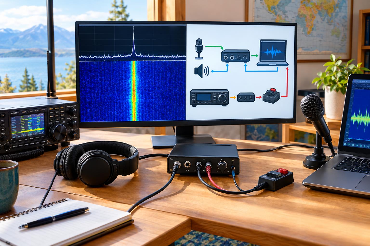
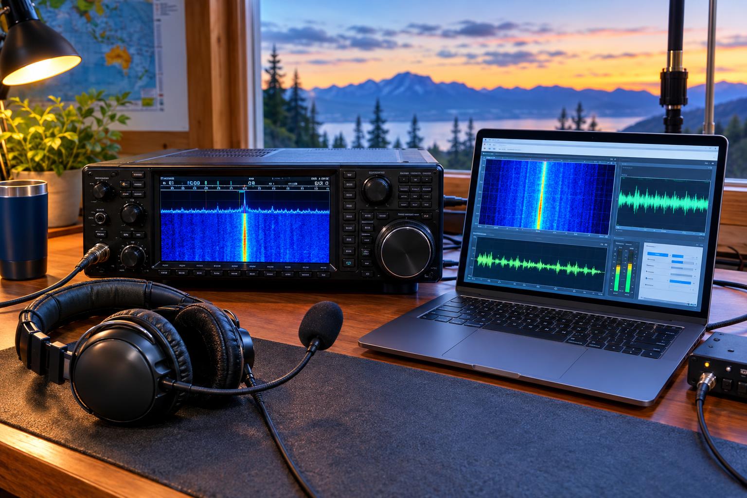
That attention also means more operators will arrive at a net with new software, unproven audio routing, and unfamiliar rig control. A good FreeDV RADE setup is not just “install the program and transmit.” It is a chain: microphone, computer audio, FreeDV, CAT/PTT control, radio audio input, RF output, receive audio, decoding, and an agreed fallback if something fails.

FreeDV 2.4.1 was released in late October 2026, and the project notes audio, rig-control, and stability fixes in the release announcement at freedv.org. That makes this a good time to check the basics before calling CQ on a RADE net.

The Goal: Clean Digital Voice, Not Maximum Loudness

HF digital voice is less forgiving of sloppy audio than casual SSB ragchewing. If the transmit path is overdriven, compressed, clipped, or routed through the wrong sound device, the receiving station may hear nothing useful even though your RF signal looks strong. The goal is a clean, linear path from the software to the transmitter, with enough drive to produce proper RF output but not enough to trigger heavy ALC action or distortion.

Start by thinking of RADE as a mode that needs disciplined audio levels. Your transceiver, sound interface, and operating system all have gain controls. If any one stage is too hot, you can create distortion that no amount of RF power will repair. If any stage is too low, the transmitter may produce little output or the decoder at the far end may struggle.

Before Net Night: Update and Confirm the Basics

Do not use a scheduled net as your first installation test. Install or update FreeDV early enough that you can solve driver, device, and permission problems without tying up the frequency. The FreeDV user manual is maintained at github.com/freedv/freedv-gui and should be your first reference for current controls, supported modes, and rig-control behavior.

  • Confirm the version: Use a current FreeDV build appropriate for your operating system.
  • Select the correct mode: Choose RADE only if that is the mode announced for the net or test.
  • Check audio devices: Identify the microphone input, speaker output, radio receive input, and radio transmit output by name.
  • Disable audio “enhancements”: Operating-system noise suppression, echo cancellation, automatic gain, and virtual surround processing can damage digital-mode audio.
  • Back up a working configuration: If you already have a stable FreeDV setup, note the settings before experimenting.

Audio-Level Preflight

Receive Audio

On receive, your radio audio must reach FreeDV at a usable level without clipping. If the signal is too low, decoding may be intermittent. If the audio input clips, the waveform is damaged before the decoder sees it. Use your interface and FreeDV level indicators as your primary guide rather than guessing by speaker volume.

  • Set the radio to the mode and filter width recommended for the net or the FreeDV documentation.
  • Turn off receive audio processing that reshapes the passband unless the manual or experienced net control recommends it.
  • Use moderate RF gain and AGC settings. Extreme AGC pumping can make weak-signal decoding harder.
  • Keep the computer input level comfortably below clipping during strong received signals.

If you are using a radio with a USB audio codec, remember that the front-panel speaker volume may not control the USB audio level. Many radios have separate menu items for USB audio output and input. Those menus are easy to overlook.

Transmit Audio

Transmit audio is where most net-night trouble starts. For digital voice, you usually want the transceiver to behave like a clean linear transmitter, not like a processed SSB voice station. Speech compression, transmit equalizers, aggressive noise reduction, and high microphone gain can all be wrong tools in this context.

  • Use the radio’s DATA, USB-D, or equivalent mode if that is the correct choice for your transceiver and setup.
  • Turn speech processing or compression off unless the FreeDV documentation for your exact path says otherwise.
  • Start with low audio drive and increase gradually.
  • Watch ALC. A little indication may be normal on some radios, but heavy ALC action is a warning sign.
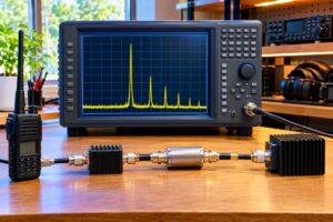
  • Use a dummy load for initial RF output checks when possible.

A practical method is to set RF power lower than your final operating level, key the transmitter briefly into a dummy load, and raise the software or interface transmit level until the radio produces expected power without obvious overdrive. If you must test on the air, use an open frequency, identify properly, keep transmissions short, and avoid interfering with ongoing QSOs.

Rig-Control and PTT Checks

CAT control is convenient, but it is another failure point. A FreeDV RADE setup can fail because the software cannot read the VFO, cannot key PTT, keys the wrong radio, or keys through VOX when you expected CAT PTT. Before a net, verify control deliberately.

  • Read test: Confirm FreeDV can read the radio’s frequency and mode if you have enabled CAT.
  • Change test: If you allow software frequency control, make a small, harmless change and confirm the radio follows.
  • PTT test: Verify whether PTT is controlled by CAT, serial RTS/DTR, a sound-card interface, or VOX.
  • Fail-safe test: Know how to stop transmit immediately if the software hangs or the PTT line sticks.
  • Port check: Make sure logging software, rig-control utilities, and FreeDV are not fighting for the same serial port.

VOX can work in some stations, but it can also cause clipped syllables, accidental transmissions, and confusing behavior when computer alert sounds leak into the transmit path. For net operation, a positive PTT method is usually easier to manage.

Frequency, Band Plan, and Operating Discipline

Net announcements may specify a dial frequency, mode, offset, or calling procedure. Treat those details as time-sensitive. Do not assume a frequency from an old forum post is still correct. Stay within your license privileges, the applicable band segment, and current rules. In the United States, consult FCC Part 97 and current band-plan guidance; outside the United States, follow your regulator and local amateur-radio practice.

Digital voice does not remove ordinary amateur obligations. Identify as required. Avoid transmitting over existing activity. Leave enough spacing for the occupied bandwidth of the mode being used. If the net control station asks for short calls, give a short call. If they ask stations to call by call-area, follow that structure.

A Simple Net-Night Workflow

Use this sequence 20 to 30 minutes before the net, not after net control starts taking check-ins.

  • 1. Launch FreeDV: Confirm the expected audio devices and RADE mode are selected.
  • 2. Verify receive: Tune to a known signal or the net frequency and watch for sane levels.
  • 3. Confirm radio mode: Use the filter, sideband, and data setting appropriate for your radio and the net instructions.
  • 4. Test CAT: Confirm frequency readout and PTT behavior.
  • 5. Check RF output: Use low power first. Watch power, ALC, SWR, and temperature.
  • 6. Prepare identification: Be ready to give your call clearly by voice or as directed by the net.
  • 7. Listen first: Copy the flow of the net before transmitting.
  • 8. Call briefly: Use your call sign and avoid long explanations until acknowledged.

Build a Fallback Plan Before You Need It

A fallback plan is not pessimism. It is good net procedure. Digital voice nets can be affected by software crashes, bad levels, incorrect mode selection, QRM, fading, and simple misunderstanding. Decide in advance how you will recover.

  • SSB fallback: Know whether the group uses USB/LSB voice on the same dial frequency, a nearby coordination frequency, or another announced channel.
  • Time fallback: Agree to return to analog voice at a specific minute if digital check-in fails.
  • Messaging fallback: If the group uses an email list, reflector, chat, or web page for coordination, have it open before the net.
  • Station fallback: If CAT fails, know how to key manually and tune the radio without software control.
  • Audio fallback: Keep a saved profile for your last known good non-RADE FreeDV mode or analog SSB settings.

The most important fallback is procedural clarity. If you transmit three long RADE calls and nobody decodes you, do not keep repeating forever. Return to the announced backup method, check your levels, and ask for a short report from a station that can monitor you.

Common Problems and What They Usually Mean

“I Have RF Output, but Nobody Decodes Me”

Suspect wrong mode, wrong sideband or data setting, distorted transmit audio, excessive ALC, or being off the net’s expected frequency. Reduce drive, confirm RADE selection, and verify the radio is not applying speech processing.

“I Decode Others, but They Cannot Decode Me”

Your receive path may be fine while your transmit path is wrong. Check the selected transmit audio device. Many computers have multiple similar device names, and an update can change the default device unexpectedly.

“PTT Keys, Then Stays Keyed”

Know the emergency stop: the radio’s power button, PTT release, interface disconnect, or software transmit toggle. After stopping, check CAT settings, serial control lines, and whether another program is asserting PTT.

“The Signal Sounds Loud, but Copy Is Bad”

Loud is not the same as clean. Digital modes need waveform integrity. Look for clipping, compression, audio enhancements, or a receive filter that is too narrow or badly centered.

FAQ

Do I need a special radio for FreeDV RADE?

Usually, the key requirement is a stable SSB-capable HF station with suitable computer audio and PTT control. A radio with built-in USB audio makes wiring easier, but external sound interfaces are also common. Always follow the current FreeDV manual for supported configurations.

Should I run full power?

Not as a first step. Start low, verify clean audio and acceptable SWR, then use only the power needed for the contact or net conditions. Watch duty cycle and heat. Some digital voice operation can keep the transmitter working harder than casual SSB speech peaks.

Can I use my normal SSB microphone settings?

Maybe, but do not assume they are correct. SSB processing that helps punchy analog voice can hurt digital audio. Build a separate radio memory or software profile for FreeDV if your equipment allows it.

Is RADE guaranteed to beat SSB in weak conditions?

No. Propagation, interference, station setup, mode settings, and operator procedure all matter. RADE is an interesting HF digital voice option, not a guarantee of copy under every condition.

Key Takeaways

  • A reliable FreeDV RADE setup depends on clean audio, not maximum gain.
  • Verify receive levels, transmit levels, CAT control, and PTT before the net starts.
  • Disable audio processing that can clip or reshape the digital waveform.
  • Use current documentation and net instructions rather than old frequency or setup notes.
  • Have an analog SSB or coordination fallback ready before calling CQ.
  • Operate within your privileges, identify properly, and avoid interfering with existing activity.

RADE net night is much more enjoyable when your station is predictable. Spend a few minutes on audio levels, rig control, and fallback planning, and you will arrive ready to participate instead of troubleshooting on frequency.
Posted on — Leave a comment

ISS SSTV This Week: Decode ARISS Series 35, Then Verify Whether the Repeater or 437.825 MHz APRS Is Active

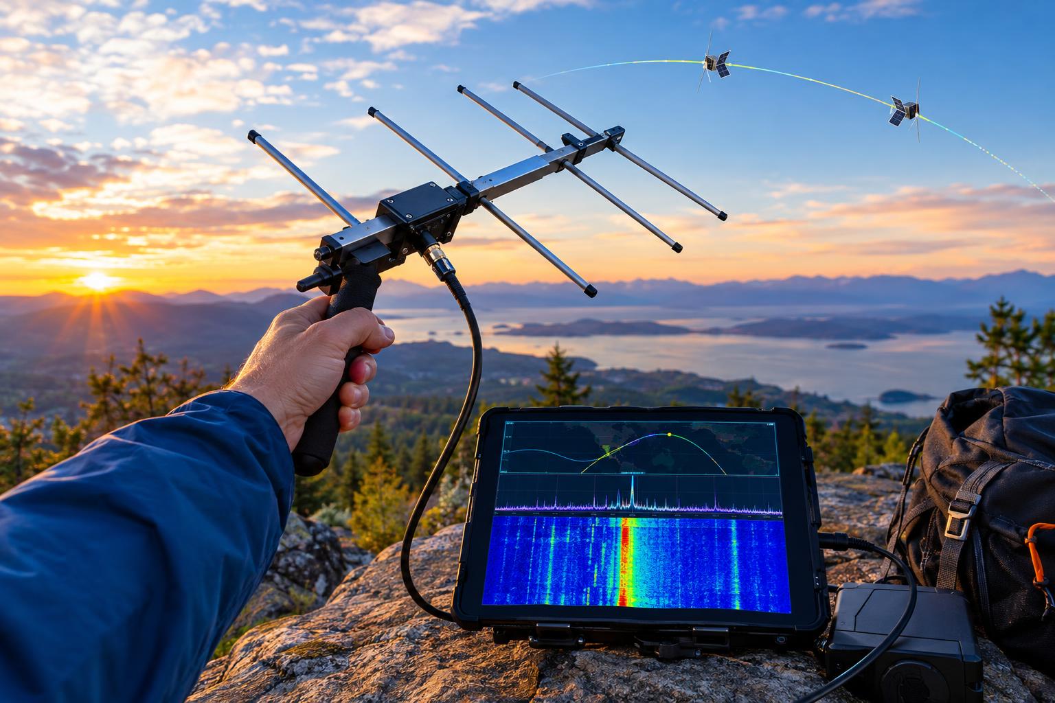
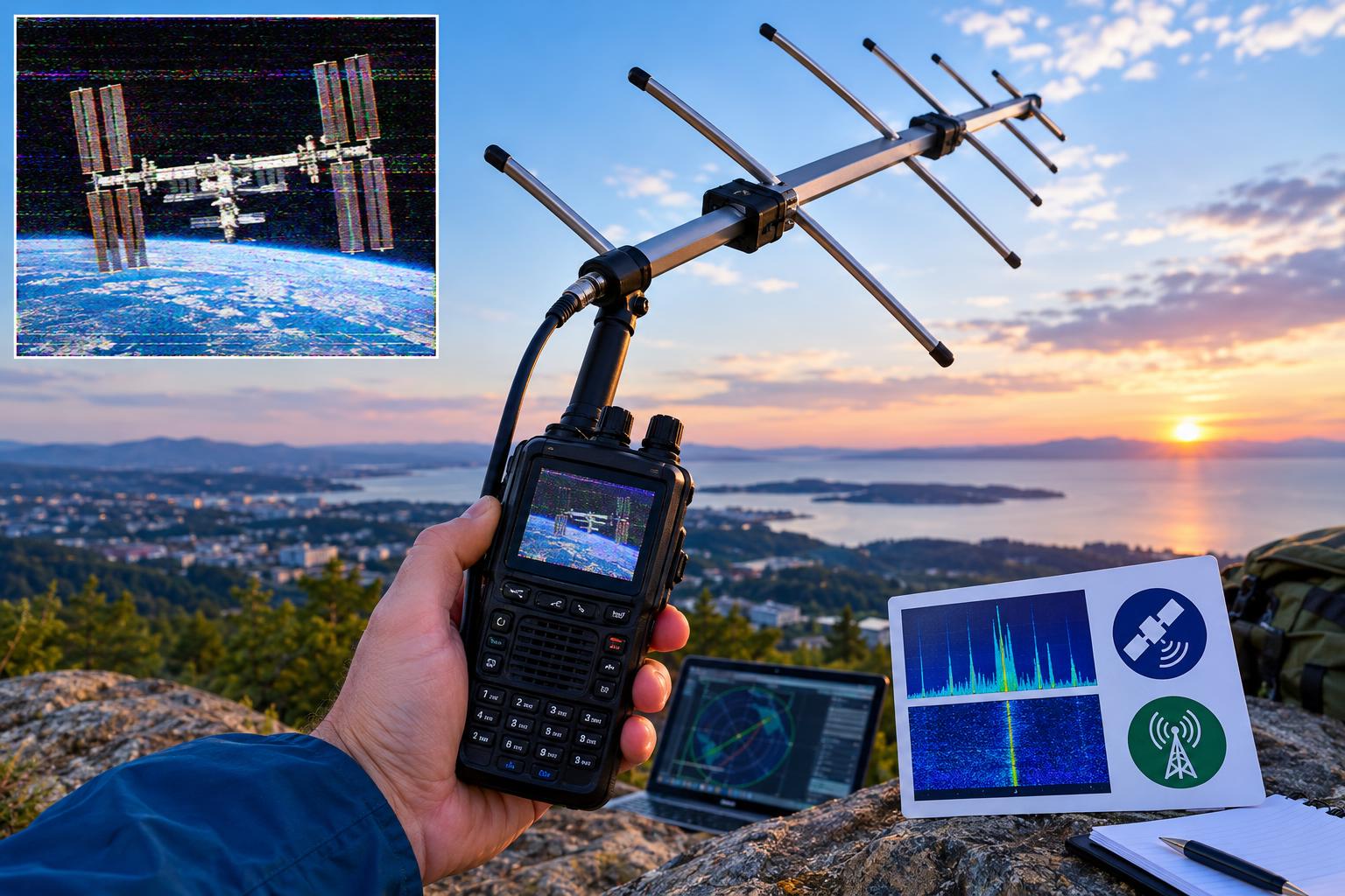
ARISS Series 35 SSTV ISS activity gives amateur radio operators and shortwave listeners a practical reason to point an antenna at the International Space Station this week. ARISS scheduled the Series 35 slow-scan television event for November 9–16, 2026, with images downlinked from the ISS for ground stations to receive and decode. The important operating detail is simple: SSTV is a receive-only opportunity for most ground stations. Do not assume the ISS cross-band repeater, packet digipeater, or 437.825 MHz APRS channel is available just because you have used it on a previous pass.

ISS amateur radio modes change as crew schedules, school contacts, station hardware, and ARISS operations require. Before you transmit, verify the current configuration on the official ARISS status pages. That habit prevents accidental transmissions on the wrong uplink, protects scheduled operations, and makes you a better satellite operator.

What ARISS Series 35 SSTV Is

Slow-scan television, or SSTV, sends a still image as audio tones over an FM voice channel. During an ISS SSTV event, the station transmits one image at a time, then pauses before the next image. A ground station receives the FM audio and feeds it to decoding software or a phone app, which reconstructs the picture line by line.

For ARISS Series 35, use the official ARISS announcement as the starting point: ARISS News Release No. 26-67. Event dates, timing, and operational notes can change, so treat the announcement and later ARISS updates as authoritative over memory, social media posts, or old frequency lists.

The typical ARISS SSTV downlink is 145.800 MHz FM, and the commonly used SSTV mode for recent ARISS image events has been PD120. However, always confirm the details for the specific event. If your decoder does not automatically detect the mode, PD120 is a sensible first setting only when it matches the current ARISS instructions.

Receive First: A Clean SSTV Setup

You do not need a large satellite station to receive ISS SSTV, but you do need a pass with decent elevation, a stable FM receiver, and clean audio into the decoder. A handheld radio can work with a suitable antenna, but a computer-controlled VHF receiver, SDR, or all-mode VHF rig often makes recording and later decoding easier.

Basic receive checklist

  • Track a real ISS pass: Use a current satellite tracking app or orbital prediction program for your location. Favor passes with higher maximum elevation.
  • Tune the downlink: Start with the announced SSTV downlink, commonly 145.800 MHz FM for ARISS SSTV events when confirmed.
  • Use the right antenna: A handheld dual-band Yagi, turnstile, eggbeater, vertical, or modest outdoor VHF antenna can work. Handheld directional antennas often improve signal quality on low-power receive setups.
  • Record the full pass: Record audio even if your live decode looks poor. You can often replay the recording into decoding software after the pass.
  • Keep audio clean: Avoid overdriving the decoder. Distorted audio produces slanted, torn, or washed-out images.
  • Disable transmit features: Turn off VOX, packet transmit, APRS beaconing, automatic ID functions, and any software that might key your transmitter.

For many operators, the best first pass is not the lowest one on the schedule. A high pass gives the receiver more time above local obstructions, and the signal is generally easier to copy. If you are using an SDR, record the baseband or demodulated audio so you can try different audio levels and filters later.

Handling Doppler Without Overcomplicating It

The ISS is in low Earth orbit, so Doppler shift is real. On 145 MHz, the shift is only a few kilohertz across a pass. Many FM receivers are wide enough that you can leave the radio on the published VHF downlink and still decode successfully, especially with a clean signal. If your receiver uses narrow filtering or you are chasing a marginal pass, small tuning adjustments may help.

On UHF downlinks and uplinks, Doppler is more significant. Around 437 MHz, the shift can be roughly plus or minus 10 kHz over a pass. That matters more for the FM repeater downlink and any UHF packet or APRS operation than it does for VHF SSTV receive. Use satellite memories or CAT control when available, but do not let automation replace checking the current ARISS mode.

After SSTV: Do Not Guess the Active ISS Radio Mode

The core operating problem this week is not only receiving images. It is knowing when not to transmit. The ISS amateur station can support different modes, but those modes are not all guaranteed active at the same time. ARISS may configure radios for SSTV, school contacts, cross-band FM repeater service, packet, or other operations. Hardware location also matters: ARISS status pages distinguish details for equipment associated with the Columbus module and the Zvezda service module.

Before transmitting, check the ARISS Current Status of ISS Stations. That page is the best first stop for current mode information. If it says the repeater is off, do not call on the repeater uplink. If it lists APRS details for 437.825 MHz, read the whole entry rather than assuming it behaves like the older 145.825 MHz ISS packet setup.

Common mode confusion to avoid

  • SSTV downlink is not an uplink invitation: During an SSTV event, receive the image transmission. Do not transmit on the downlink frequency.
  • The FM repeater has separate uplink and downlink frequencies: When active, the ISS cross-band repeater is not worked by transmitting on its downlink.
  • APRS frequency depends on the current station configuration: ISS packet history includes familiar VHF APRS operation, but current ARISS information may list Zvezda APRS on 437.825 MHz. Verify before beaconing.
  • Old memory channels can be wrong: A radio memory programmed months ago may not match this week’s active ISS mode.

Verifying the Columbus FM Repeater

The ISS FM repeater, when active, is a cross-band satellite repeater. Operators typically receive on UHF and transmit on VHF, using the uplink tone specified by ARISS. The ARISS status page has listed Columbus repeater details, including frequency and tone information, but you should always check the page immediately before operating because the repeater can be disabled for SSTV, school contacts, maintenance, or crew activities.

If the repeater is active, operate like a courteous satellite user. Listen before transmitting. Use minimum practical power for your station and pass geometry. Give your call sign clearly. Make short exchanges. Do not whistle, tune up, or repeatedly key the uplink just to see whether you can hear yourself. The repeater footprint is large, and one poor operating habit can cover other stations over a wide area.

Also remember Doppler. On a UHF downlink, you may need several receive memories or continuous tuning across the pass. If you hear stations clearly but cannot get in, do not automatically increase power. Check the published uplink, CTCSS tone, antenna polarization, pass geometry, and whether the repeater is still active.

Verifying 437.825 MHz APRS

The research item many operators will notice is 437.825 MHz APRS. ARISS USA maintains an APRS information page at ARISS APRS, and the ARISS station status page should be checked for the currently active module, frequency, packet path, and any operational notes. Do not assume that every APRS client, TNC, or handheld APRS radio is configured correctly just because it worked through terrestrial digipeaters.

APRS via the ISS is still amateur packet radio. You need the proper license privileges for your jurisdiction, a valid call sign, suitable path settings as specified by ARISS, and clean AFSK audio or a correctly configured packet modem. Keep packets brief. Disable excessive beacon rates. Do not transmit long messages repeatedly into a single pass. The ISS is moving quickly, and channel time is limited.

Before sending an APRS packet

  • Confirm that ARISS currently lists APRS as active for the station you intend to use.
  • Confirm whether the active APRS frequency is 437.825 MHz or another officially listed frequency.
  • Set Doppler compensation appropriate for UHF if your equipment requires it.
  • Use the ARISS-specified path, not a random terrestrial APRS path.
  • Send one concise beacon or message, then listen for results instead of flooding the channel.

A Practical This-Week Workflow

For an operator who wants to enjoy ARISS Series 35 and still be ready for repeater or APRS operation later, the safest workflow is sequential.

  • Step 1: Check the ARISS event release. Confirm the Series 35 event window, intended SSTV mode, and downlink notes.
  • Step 2: Build a receive-only SSTV profile. Program the SSTV downlink, configure your decoder, and disable every transmit automation feature.
  • Step 3: Record several passes. Try high-elevation passes first. Save audio files so you can re-decode them later.
  • Step 4: After the SSTV pass, check official status again. Do not rely on what was active yesterday.
  • Step 5: If a transmit mode is active, load the correct profile. Use a separate radio memory bank or software profile for repeater and APRS operations to avoid accidental cross-use.
  • Step 6: Monitor before transmitting. If the channel behavior does not match the published mode, stop and re-check.

This workflow is intentionally conservative. It separates receiving from transmitting, which reduces the chance that an APRS beacon, VOX setting, or repeater uplink memory will key up while you are trying to decode SSTV audio.

Safety, Licensing, and Good Amateur Practice

Receiving ISS SSTV does not require transmitting and is generally open to anyone with suitable receive equipment. Transmitting to the ISS amateur station is different. In the United States, you need an appropriate FCC amateur radio license and must follow the applicable Part 97 rules, including identification and authorized emissions. Operators outside the United States should follow their own regulator’s rules and local band plans.

Use practical RF safety judgment. Handheld satellite antennas are commonly used at low power, but higher-power fixed stations require attention to RF exposure compliance, feed line losses, antenna placement, and bystander access. Outdoor antennas should be installed with proper mast safety, weather protection, and lightning considerations. Never adjust an elevated antenna while distracted by a fast-moving satellite pass.

FAQs

Can I transmit during ARISS Series 35 SSTV?

For the SSTV activity itself, treat the operation as receive-only unless ARISS explicitly publishes otherwise. The SSTV downlink is for receiving images. Do not transmit on that frequency.
Is 437.825 MHz definitely active for ISS APRS this week?

Do not assume. The ARISS status page may list Zvezda APRS details including 437.825 MHz, but status can change. Confirm immediately before transmitting and follow the current ARISS APRS instructions.

What if I only decode part of an image?

Partial images are common on low passes, obstructed horizons, or noisy receive setups. Save the audio recording, adjust the level, and try decoding again. A higher pass and a directional antenna often help more than changing software.

Where can I learn more about amateur radio on the ISS?

AMSAT maintains a useful overview at Amateur Radio on the ISS. Use it for general context, and use ARISS pages for current operational status.

Key Takeaways

  • ARISS scheduled Series 35 SSTV for November 9–16, 2026; verify the latest event details with ARISS.
  • Receive SSTV first, preferably recording the pass for later decoding.
  • Do not transmit on SSTV downlink frequencies.
  • Before using the ISS FM repeater or APRS, check the ARISS Current Status page.
  • 437.825 MHz APRS requires current confirmation, correct configuration, and disciplined packet operating.
  • Separate receive-only SSTV profiles from transmit-capable repeater or APRS profiles to avoid mistakes.

The best ISS operators are patient listeners. Decode the Series 35 images, enjoy the event, and then verify the active ARISS mode before making any transmission.

Posted on — Leave a comment

CQ WW CW 2026 Prep: 48-Hour Log Deadline, No Autonomous Robots, and a Clean Beginner Contest Logger Workflow

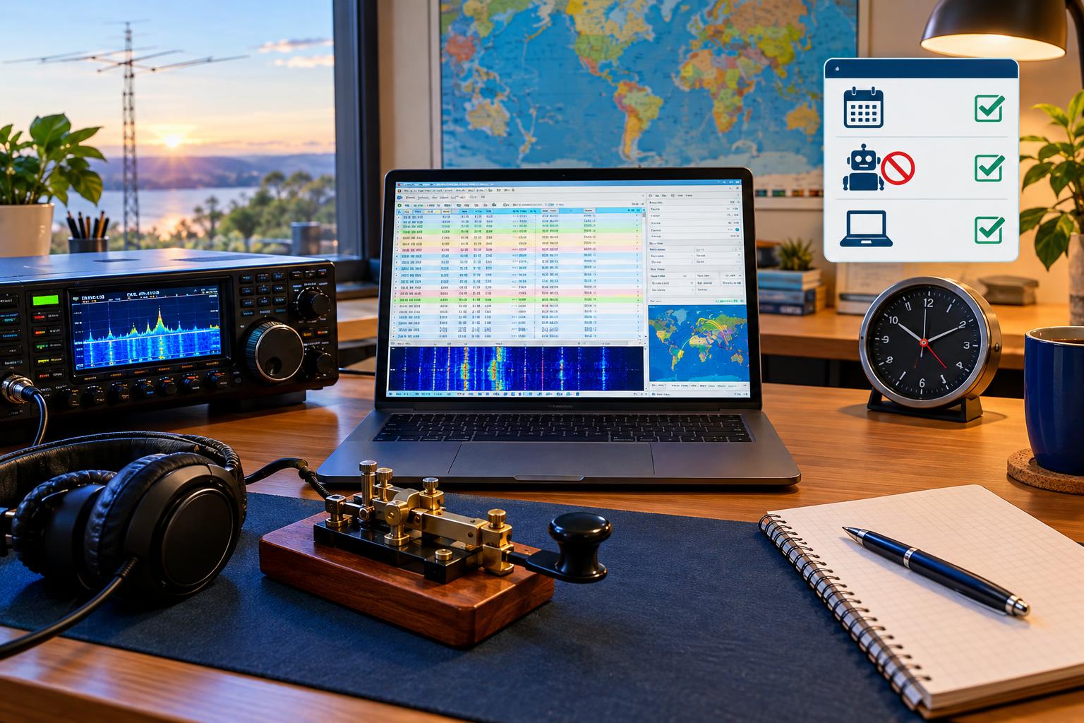
The most important CQ WW CW 2026 rules change for everyday operators is not about antennas, power, or propagation. It is about time and control: logs are due within 48 hours after the contest, and autonomous robot operation is formally prohibited. For a casual or first-time CW contester, those two items change the workflow. You cannot wait several days to clean up a log, and you should not use any system that makes contest QSOs without direct human operation.

The good news is that a compliant process is simple if you set it up before the first CQ. This guide walks through category choice, exchange practice, clean logging, and the post-contest steps that help you submit a valid Cabrillo log on time. Always confirm details against the official CQ WW rules and the CQ WW 2026 rule changes announcement, because the sponsor’s current published rules control.

What Changed for 2026

CQ WW announced that, beginning with the 2026 contests, logs must be submitted within 48 hours after the contest ends. For CQ WW CW, the contest is traditionally held on the last full weekend of November, from 0000 UTC Saturday through 2359 UTC Sunday. If the official 2026 CW weekend remains November 28-29, that 48-hour window points to a deadline around 2359 UTC on Tuesday, December 1, 2026. Treat that as a planning example, not a substitute for checking the official contest page.

The other major 2026 change is the formal prohibition on autonomous robot operation. In practical terms, the operator must remain the real-time decision maker. Contest software may help you send CW memories, track dupes, display band maps, and prepare a Cabrillo file. But an unattended or self-directed system that finds stations, calls them, copies exchanges, logs contacts, and moves on without operator control is outside the spirit and now the stated rule framework.

Start With the Correct Category

Many logging problems begin with an uncertain category. Choose your category before the contest and configure the logger to match it. For a first serious CQ WW CW effort, the simplest path is usually a single-operator category using one station, one transmitted signal at a time, and a clearly defined power level. If you use packet spots, RBN spots, a cluster, or a band map populated by external spotting data, make sure your selected category allows assistance.

Common decisions include:

  • All band or single band: All band is flexible and educational. Single band is simpler if your antenna system works well on one band or your available time is limited.
  • Assisted or unassisted: If you use spotting information, enter an assisted category unless the current rules define your situation differently.
  • High, low, or QRP power: Configure the category to match actual transmitter output and your license privileges. Low power in many HF contests is commonly 100 watts or less, but verify the CQ WW definition for the year you operate.
  • Single operator or multi-operator: If more than one person operates, logs, spots, or makes operating decisions as part of the entry, review the multi-operator rules carefully.
  • Overlays: If you claim an overlay such as Classic, Rookie, Youth, or another offered option, confirm eligibility and operating limits before the contest.

A conservative beginner rule is this: if you are unsure whether a tool or helper changes your category, assume it does until you verify otherwise in the official rules.

Know the Exchange Before You Call CQ

CQ WW CW uses a short exchange: signal report plus CQ Zone. On CW, the signal report is normally sent as 599, followed by the zone number. A U.S. station in CQ Zone 5 would typically send “599 05.” A station in Zone 4 would send “599 04.” Your logger should know your zone before the contest starts.

Do not confuse CQ Zones with ITU Zones, states, sections, grid squares, or counties. The zone is a multiplier, and an incorrect received zone can cost points or produce log-checking penalties. Many logging programs prefill expected zones based on call sign, but you are still responsible for logging what was actually received. If the station sends a different zone than expected, copy the exchange and correct your log only when you are confident.

Practice a Realistic CW Rhythm

Before the contest, practice both search-and-pounce and running. Search-and-pounce means tuning the band, finding a station calling CQ, and answering. Running means you call CQ and work stations that answer you. Beginners often start with search-and-pounce because it reduces pressure, but a short run on a clear frequency can teach more about timing than an hour of tuning.

A clean search-and-pounce contact might sound like this:

  • DX station: CQ TEST PJ2T PJ2T
  • You: W1ABC
  • DX station: W1ABC 599 09
  • You: 599 05
  • DX station: TU PJ2T

Log the exact call sign, band, time, mode, and received zone. If you are not sure the station returned your full call, call again or wait. A fast but uncertain QSO is not better than a slightly slower valid one.

Build a Clean Beginner Logger Setup

Any capable contest logger should be able to create a CQ WW CW log and export Cabrillo. Popular contest loggers differ in menus and terminology, so avoid relying on memory the night before. Create the contest file early and verify these items:

  • Contest type: Select CQ WW CW, not CQ WW SSB, a domestic contest, or a generic DX log.
  • Your call sign: Enter the call sign you will actually use on the air, including any portable identifier if applicable and permitted.
  • CQ Zone: Confirm your transmitted zone.
  • Category: Match assisted status, band choice, power level, operator count, and overlay claims.
  • Station location: Confirm country, state, and other required Cabrillo header fields.
  • Radio interface: If using CAT control, verify that band and frequency changes are recorded correctly.
  • CW keying: Test memories into a dummy load or monitor sidetone, not on a live frequency.
  • Computer clock: Synchronize time before the contest. UTC accuracy matters in log checking.
  • Backups: Know where the log file is stored and how to make a quick copy during breaks.

Use CW memories to reduce typing errors, but keep them operator-controlled. A memory that sends your call, exchange, or “TU” when you press a key is normal contest practice. A system that decides who to call and completes contacts without your immediate control is a different matter.

Operate Within the Rules and Your License

CQ WW is an amateur radio contest, so contest rules do not replace government regulations. U.S. operators must stay within FCC Part 97 privileges, band edges, power limits, identification rules, and RF exposure requirements. International operators must follow their own regulator’s rules. The contest may use the major HF contest bands, but WARC bands are not contest bands. Stay out of segments where your license class, mode, or local band plan does not permit CW operation.

Safety also matters during a 48-hour event. Do not adjust antennas in the dark or bad weather just to chase a multiplier. Keep amplifier, tuner, and power supply ventilation clear. If you operate with temporary antennas, secure feed lines, use appropriate strain relief, and keep people away from energized conductors and high-RF areas. Fatigue can cause both logging mistakes and unsafe station decisions, so schedule rest.

What “No Autonomous Robots” Means in the Shack

The 2026 autonomous-robot rule is especially relevant because modern stations can combine skimmers, decoders, band maps, CAT control, macros, and remote access. Not all automation is prohibited. Contest logging assistance has existed for years. The dividing line is whether the licensed operator is actively controlling the QSO process.

Generally low-risk examples include:

  • CW memories that send messages when the operator presses a key.
  • Dupe checking and multiplier highlighting.
  • CAT control that records the current band and frequency.
  • Spotting data used in a category where assistance is allowed.
  • Post-QSO error checking before Cabrillo export.

High-risk or prohibited examples include:

  • An unattended station that automatically calls spotted stations and logs replies.
  • Software that completes contest exchanges while the operator is away.
  • A self-directed “agent” that chooses bands, selects targets, transmits, and confirms QSOs without real-time human decisions.
  • Any setup designed to create contacts after the operator has stopped actively operating.

If a feature makes you wonder whether you are still operating or merely supervising a robot, do not use it until you have a clear answer from the current rules or the contest sponsor.

During the Contest: Log for Accuracy First

The best post-contest workflow is a clean live log. Enter each call sign carefully. Watch for common CW copying problems: H/5, S/H, B/6, U/V, and cut numbers in serial-like exchanges. CQ WW does not use a serial number, but zones may be sent quickly or with leading zeroes. If you copy “5NN 4,” your logger may record Zone 4; if the expected zone is different, pause long enough to be sure.

Fix obvious mistakes during the contest when you have reliable information. For example, if you typed K1ABC but immediately realize the station repeatedly sent K1ABD, correct it. Do not invent a zone later because a database says it is likely. Log what was exchanged. If a contact is doubtful, it is better to leave an honest log than to manufacture certainty after the fact.

The 48-Hour Post-Contest Workflow

Because the log deadline is short, plan to submit before Monday night in U.S. time zones if possible. A simple post-contest checklist looks like this:

  • Save a backup immediately: Copy the native logger file before editing anything.
  • Review station data: Confirm call sign, category, operators, power, club if claimed, and location fields.
  • Check obvious entry errors: Look for blank exchanges, impossible bands, accidental SSB entries, or duplicate contest files.
  • Do not over-edit: Correct clear logging mistakes, but do not use outside information to rewrite uncertain QSOs.
  • Export Cabrillo: Use the logger’s Cabrillo export for CQ WW CW.
  • Open the file: Confirm that the header and QSO lines appear reasonable in a plain text editor.
  • Submit online: Use the official CQ WW log submission page.
  • Save confirmation: Keep the email or web confirmation with your station notes.

Do not wait for the last hour. Internet problems, a missing category field, or a Cabrillo formatting warning can turn a simple submission into a stressful scramble. The official upload system is the correct place to learn whether your file passes basic formatting checks.

After Results: Use Your LCR to Improve

Once results and reports are available, the CQ WW public log checking reports can be very useful. A log checking report may show busted calls, incorrect exchanges, not-in-log contacts, duplicates, and scoring changes. Read it as a training document, not as a punishment. If most errors are busted calls, slow down your call sign copying. If exchange errors dominate, practice zone recognition. If many contacts are not in the other station’s log, review timing and whether you transmitted over another caller.

Key Takeaways

  • The CQ WW CW 2026 rules include a 48-hour log deadline, so prepare your Cabrillo workflow before the contest.
  • Autonomous robot operation is formally illegal; keep the operator in real-time control of QSOs.
  • Choose your category before operating, especially assisted versus unassisted and all-band versus single-band.
  • The exchange is signal report plus CQ Zone; know your own zone and copy the received zone carefully.
  • Submit through the official CQ WW log page and save confirmation.

FAQ

Can I use CW memories in CQ WW CW 2026?

Yes, ordinary CW memories controlled by the operator are a standard contesting practice. The concern is not a memory keyer; it is autonomous operation that makes QSOs without direct human control.

Can I use spotting networks?

Only if your entry category permits assistance. If you use cluster spots, RBN-derived spots, or similar external spotting data, choose the appropriate assisted category under the current rules.

What happens if I miss the 48-hour deadline?

The 2026 rule change makes timely submission critical. Check the current CQ WW rules for the sponsor’s treatment of late logs, but plan as though your competitive entry depends on submitting within 48 hours.

Should I correct my log after the contest?

Correct administrative fields and obvious logging errors, but do not reconstruct uncertain QSOs from outside databases. A contest log should reflect what was actually copied and exchanged on the air.

Posted on — Leave a comment

Try FreeDV RADE V2 on HF: Receive-First Setup, Audio Chain Checks, and Safe PTT Test Plan

FreeDV RADE V2 HF digital voice is worth approaching differently from familiar HF modes such as SSB, FT8, JS8, or PSK31. It is still amateur radio over HF, and it still depends on propagation, clean audio, legal operating privileges, and a properly adjusted transmitter. But the operating goal is live digital speech, not keyboard text and not analog single-sideband audio.

The safest way to learn it is to receive first, verify the audio chain, then perform a controlled push-to-talk test before making an on-air call. That sequence reduces the two most common digital-voice problems: no decode because the receive path is wrong, and poor transmitted signal quality because the audio chain is overdriven.

FreeDV’s 2026 posts around RADE V2, the FreeDV 2.3.x releases, and over-the-air V2 test activity make one point clear for practical operators: RADE V2 is not just another checkbox in a mode list. It deserves a deliberate station setup, especially around audio levels and PTT behavior.

What FreeDV RADE V2 Is—and What It Is Not

FreeDV is open-source digital voice software for amateur radio. RADE refers to a newer digital-voice approach using a radio autoencoder concept. In everyday station terms, you speak into a microphone, the software encodes your voice into a digital signal suitable for HF, and another station running compatible software decodes it back into speech.

That makes it different from FT8. FT8 is a weak-signal digital text mode with structured messages, time synchronization, and automated sequencing conventions. FreeDV RADE V2 is intended for voice communication. It is also different from ordinary SSB because the transmitted audio is not your voice waveform; it is a digital waveform carrying encoded speech.

For the operator, this means:

  • Do not use SSB speech processing, aggressive transmit EQ, or compression as if you were trying to punch through a pileup.
  • Do not expect FT8 software, FT8 waterfall habits, or FT8 frequencies to apply.
  • Do treat the signal as an HF digital voice emission that needs clean audio, stable tuning, and correct PTT control.
  • Do check your license privileges, band segment, and applicable rules before transmitting.

Start With a Receive-First Station Plan

A receive-first setup lets you learn the software and signal flow without putting a questionable signal on the air. It also helps you separate three different problems: RF reception, computer audio routing, and FreeDV configuration.

Basic receive path

A typical receive chain is:

  • Antenna to HF transceiver.
  • Transceiver receive audio to computer audio input, USB sound device, or built-in USB audio codec.
  • Computer input device selected in FreeDV.
  • FreeDV mode set to RADE V2 when available in your installed version.
  • Decoded audio routed to headphones or speakers.

If your radio has a data or USB-D mode that provides flat receive audio and predictable routing, it is often a good starting point. If you use ordinary USB voice mode, keep the receive filter wide enough for the selected FreeDV signal and avoid narrow voice tailoring that removes important parts of the digital waveform. Exact menu names vary by radio, so rely on your radio manual rather than a generic checklist.

What to check before chasing signals

Before trying to decode a live signal, confirm that FreeDV is receiving audio from the intended device. Many failures are simply the wrong sound card, a muted input, or the operating system assigning a different device after a reboot.

  • Select the radio’s receive audio device, not the laptop’s internal microphone.
  • Disable system enhancements such as noise suppression, automatic gain, or conferencing effects on the radio audio path.
  • Use headphones while troubleshooting to avoid acoustic feedback and room noise confusion.
  • Verify that the FreeDV input meter responds to receiver noise when the radio volume or USB audio level is adjusted.
  • Keep the receive level moderate; an input slammed against full scale can prevent reliable decoding.

If the software supports stored-file playback or test files for the mode you are using, that can be useful for learning the interface without depending on current band conditions. FreeDV’s May 2026 V2 stored-file test campaign is a good example of why repeatable receive material matters: it lets developers and operators compare behavior without changing every variable at once.

Dial Frequency, Sideband, and Tuning Discipline

FreeDV over HF normally rides through an SSB transceiver passband. In many HF digital setups, upper sideband is used regardless of band, but you should follow current FreeDV guidance, current band plans, and the actual operating practice of the group you are joining. Avoid publishing or relying on old frequency lists as if they are permanent.

For initial receive tests, your job is not to transmit; it is to tune carefully and observe. Use the radio’s frequency control, waterfall, and FreeDV indicators together. If your radio has high stability, leave it alone once centered. If the signal is marginal, avoid constantly chasing the waterfall unless you know the signal is drifting. Over-tuning can make a decodable signal worse.

Audio Chain Checks Before Any Transmission

Digital voice rewards clean, boring audio. The goal is not loudness. The goal is an undistorted waveform reaching the transmitter at the correct level.

Transmit audio path checklist

Before enabling RF output, trace the intended transmit chain:

  • Microphone or headset into FreeDV.
  • FreeDV encoding output to the selected transmit audio device.
  • Computer audio output into the radio’s USB audio input, data input, accessory input, or sound-card interface.
  • Radio set for the correct input source.
  • Speech processor, compression, transmit noise reduction, and voice equalization disabled unless FreeDV documentation specifically says otherwise.
  • VOX disabled for early tests unless you have a specific reason to use it.
  • ALC and RF power behavior observed at low drive.

Overdriving can happen in several places: microphone input into the software, software output into the operating system mixer, computer output into the radio, or radio drive into the RF chain. Reducing only the RF power control does not necessarily fix a distorted audio waveform. Set levels from the beginning of the chain forward.

ALC is a warning sign, not a target

On many radios, heavy ALC action during digital modes suggests too much audio drive. For a first FreeDV test, aim for little or no ALC movement unless your radio manual gives different guidance for its data input. Use the radio’s power meter, ALC indication, and, if available, an external wattmeter to confirm that the transmitter is behaving predictably.

Do not use microphone gain, computer output volume, and RF power as interchangeable controls. They affect different parts of the chain. A clean low-power signal is more useful than a louder distorted one.

A Safe PTT Test Plan

FreeDV’s October 2026 discussion of RADE V2 PTT tests and improvements is a reminder that PTT behavior is not a minor detail. PTT sits at the boundary between software, computer, interface, radio, and RF output. Test it deliberately.

Stage 1: No-RF software and routing check

First, confirm that the software can key the intended PTT method without generating RF. Depending on your station, this might mean using a radio transmit-inhibit setting, disconnecting PTT from the radio, or testing the serial/CAT control path with RF output disabled. Do not assume every radio has the same protection features.

  • Verify that pressing transmit in FreeDV keys only the intended radio.
  • Confirm that the radio returns to receive when PTT is released.
  • Watch for stuck transmit, delayed release, or the wrong COM port.
  • Make sure the computer will not sleep, change audio devices, or interrupt USB power during a test.

Stage 2: Dummy load at minimum practical power

Next, connect a suitable dummy load rated for the frequency and power level. Start at minimum practical RF output. This is not a coverage test; it is a station-control test.

  • Transmit briefly while speaking normal test audio into the microphone.
  • Observe RF power, SWR, and ALC.
  • Stop immediately if the transmitter shows high SWR, excessive ALC, unstable power, or unexpected audio routing.
  • Let equipment cool if the dummy load or radio duty cycle requires it.

Digital voice can have a higher duty cycle than casual SSB speech. Respect your radio’s duty-cycle guidance, power-supply limits, tuner limits, and dummy-load rating. A short, low-power test is enough to prove PTT and audio routing.

Stage 3: On-air low-power verification

Only after receive, audio, and dummy-load checks should you try an on-air call. Choose a legal frequency and mode segment for your license class and location. Use the lowest power that is reasonable for the test, avoid occupied frequencies, and identify according to current regulations. In the United States, consult current FCC Part 97 rules and accepted band plans; outside the United States, consult your national regulator.

A practical first on-air exchange is not a long QSO. It is a short request for a signal-quality report from a station prepared to receive RADE V2. If you cannot confirm that anyone is listening with compatible software, keep tests brief and avoid repeated blind transmissions.

Common Problems and Practical Fixes

No decode on receive

  • Confirm the correct input device in FreeDV.
  • Check that the radio is sending receive audio to the computer.
  • Use a wider receive filter if it is too narrow.
  • Reduce overloaded audio input levels.
  • Verify that you are using the same FreeDV mode as the transmitting station.

PTT keys the radio but no RF appears

  • Check that the radio is in the correct data or SSB mode.
  • Confirm that transmit audio is routed to the radio input actually selected.
  • Check transmit inhibit, split settings, accessory input menus, and USB audio levels.
  • Verify that RF power is not set to zero and that an external tuner or amplifier is not blocking transmit.

RF appears but reports are poor

  • Back down computer audio output and microphone level.
  • Turn off compression, processing, and transmit EQ.
  • Check for ALC overdrive.
  • Confirm antenna SWR and feed-line condition.
  • Try a shorter test at lower power to rule out heating, RF feedback, or power-supply sag.

Safety and Regulatory Caveats

HF digital voice is still RF transmission. Maintain RF exposure compliance, use safe station grounding and bonding practices, and keep antennas away from power lines. If you operate portable, secure cables, batteries, and masts so a software test does not become an electrical or trip hazard.

Legally, software capability does not equal operating permission. Confirm your license privileges, emission permissions, band allocation, and any local restrictions before transmitting. If you are testing on a shared band, listen first and avoid interfering with ongoing QSOs or established activity.

Helpful Sources

FAQs

Is FreeDV RADE V2 the same kind of operating as FT8?

No. FT8 is structured weak-signal text communication. FreeDV RADE V2 is digital voice. Both use software and HF signals, but the operating habits, audio setup, and contact style are different.

Can I use my normal SSB microphone settings?

Usually not without adjustment. Turn off speech processing and compression for initial tests, use a clean audio path, and set levels so the transmitter is not being overdriven.

Should I start by transmitting?

No. Receive first. Confirm software, audio devices, tuning, and mode selection. Then test PTT without RF if possible, followed by a brief dummy-load test before any on-air transmission.

Do I need a special radio?

Many HF SSB transceivers with suitable audio input/output and reliable PTT control can be used. The details depend on the radio, interface, computer, and software version. Consult the current FreeDV documentation and your radio manual.

Key Takeaways

  • Use a receive-first approach before transmitting FreeDV RADE V2 on HF.
  • Keep the audio chain clean, moderate, and free of speech processing.
  • Test PTT deliberately; stuck or misrouted PTT can create real on-air problems.
  • Use a dummy load and low power for initial transmit checks.
  • Do not treat RADE V2 like FT8 or ordinary SSB; it is digital voice with its own setup discipline.
  • Confirm legal privileges, band usage, identification rules, RF exposure compliance, and local regulations before going on the air.
Posted on — Leave a comment

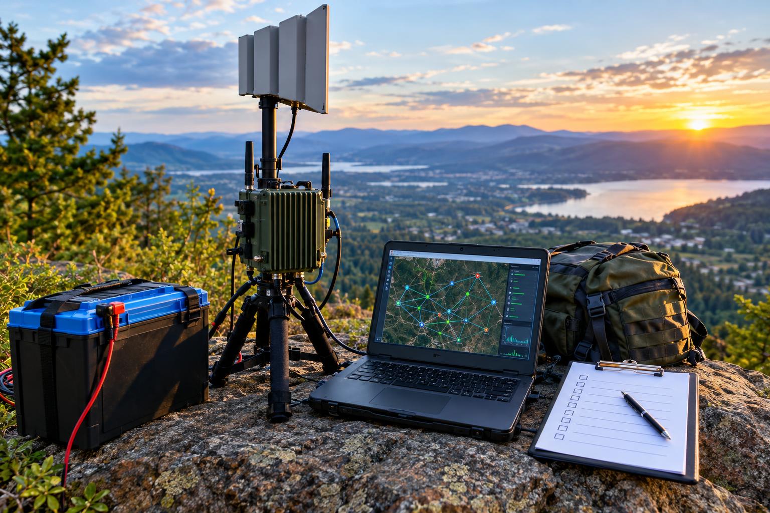
AREDN 4.26.10 Upgrade Drill: Back Up Nodes, Test Multi-Radio Mesh, and Prove an Off-Grid Service Path

Why Treat an AREDN 4.26.10 Upgrade Like a Drill?

AREDN 4.26.10.0 was released October 29, 2026, with changes called out by the project around memory improvements, multi-mesh radio support, multi-station radio support, and tunnel configuration changes. For an amateur radio emergency data network, that is not just a routine software refresh. It is a chance to prove that your team can preserve node settings, restore service advertisements, validate multi-radio paths, and operate useful applications without commercial power or Internet dependency.

The safest approach is to upgrade as though you are preparing for an emergency exercise: inventory first, back up everything, change one variable at a time, and verify actual services from a user device at the far end of the mesh. A node status page alone does not prove that a served agency form server, chat tool, or monitoring dashboard is reachable over RF.

Use the official project material as your starting point, especially the AREDN 4.26.10.0 release announcement, the AREDN changelog, the AREDN 4.26.10.0 documentation overview, and the AREDN project repository. Menu labels, supported hardware, and release behavior can change, so verify details against the current documentation before touching a production node.

Pre-Upgrade Rule: Capture the Network Before You Change It

Before installing AREDN 4.26.10, freeze the current topology on paper or in a shared file. Record each node name, call sign, location, band, channel, channel width, transmit power setting, antenna type, azimuth, PoE arrangement, and whether the node is reachable by RF, device-to-device Ethernet, LAN, WAN, or tunnel. If a node is on a tower, rooftop, hilltop, or emergency operations center mast, note how you will reach it if the upgrade does not come back cleanly.

For each node, save more than one kind of backup. Use the node’s built-in support or configuration export tools when available, but also take screenshots or notes of critical setup pages. Include network mode, LAN addressing, DHCP reservations, advertised services, hostnames, port forwards, tunnel settings, and any package or application notes. If your team uses static IP addresses for chat servers, form servers, cameras, weather stations, or monitoring hosts, document those addresses separately from the firmware backup.

A useful naming convention is simple: date, node name, site, and pre-upgrade version. Example: 2026-11-ARES-EOC-North-pre-42610. Store the files where the upgrade operator can reach them without the mesh. A backup stored only on a server behind the node being upgraded is not a backup during a failure.

Build a Small Upgrade Bench Before Touching Field Nodes

If you have spare compatible hardware, upgrade one bench node first. Confirm that the correct image type is being used for your device and that you understand the difference between first-install and upgrade images for your hardware. Keep the node on reliable power, use a wired Ethernet connection from the administration computer when practical, and do not interrupt power during flashing.

After the first bench upgrade, verify the basics: the node boots, the administrator password still works or is reset as expected, the correct version is displayed, the node name and call sign are right, the RF interface is present, and LAN clients receive addresses if the node is supposed to provide DHCP. Then restore or re-enter any service advertisements and confirm that your browser can reach them by the same names operators will use during an exercise.

The bench test should also include a rollback plan. That does not mean every node can be magically restored remotely, but the team should know where the previous firmware image, configuration files, spare PoE injectors, Ethernet patch cables, and access credentials are located. If a rooftop node is a single point of failure, do not upgrade it first.

Upgrade Order for a Live Amateur Mesh

Upgrade from the edge inward unless you have a compelling reason to do otherwise. Begin with a noncritical node that has local access and an alternate path to the network. Avoid upgrading two ends of the same important RF link at the same time. If a backbone path uses paired dish nodes, upgrade one side, verify adjacency and service reachability, then upgrade the other.

A practical order is: lab node, portable go-kit node, noncritical user access node, secondary relay node, backbone node with local access, and finally critical remote nodes. Keep a log with start time, operator, node, firmware version, power source, and result. If the team is using VHF or UHF repeaters for coordination, assign a separate net control operator so the person upgrading firmware is not also trying to manage voice traffic and troubleshooting notes.

For nodes linked through tunnels, pay special attention to the AREDN 4.26.10 tunnel configuration changes described by the project. Export or record tunnel settings before upgrading and verify peer status afterward. For an off-grid exercise, however, do not count an Internet tunnel as proof of RF survivability. Label tunnel-assisted paths clearly and test the same services again with WAN or tunnel dependency removed if the exercise objective is local emergency communications.

Test Multi-Radio Mesh Behavior Deliberately

The release notes call attention to multi-mesh radio support and multi-station radio support. In the field, that means you should not simply upgrade and assume that all radios are still serving the intended roles. A multi-radio site may include a 5 GHz backbone dish, a sector node for local users, and a separate device-to-device Ethernet connection between radios. Each interface needs its own verification.

Create a path matrix before the test. List Site A, Site B, Site C, and the services hosted at each site. Then test one path at a time. If possible, temporarily reduce variables by checking one RF link, one Ethernet device-to-device link, and one client access path separately before running the whole network. The goal is not to produce laboratory-grade throughput numbers; the goal is to prove that expected neighbors appear, routing is sane, and application traffic reaches the correct host.

For each radio path, check three layers. First, physical and RF: antennas aimed, feed lines weatherproof, PoE voltage correct, no loose shield or damaged connector. Second, mesh layer: neighbor relationship appears as expected and the route is not taking a surprising detour. Third, service layer: a user device can open chat, submit or retrieve a form, and view monitoring without manually typing obscure IP addresses unless that is part of your documented procedure.

Use SDR and Spectrum Awareness Without Overstating the Tool

Software-defined radio can help identify interference and channel activity, but the tool must match the band. Many inexpensive SDR receivers do not directly cover 2.4 GHz or 5 GHz AREDN links without additional hardware, downconverters, or a suitable spectrum analyzer. For VHF and UHF coordination channels, an SDR can be very useful for viewing repeater input or output activity, desense, nearby transmitters, or unexpected signals during an exercise.

Keep receive equipment safe. Do not connect an SDR directly to a transmitting antenna system unless you understand isolation, attenuation, and maximum input levels. A nearby handheld, mobile radio, or mesh node can overload or damage a receiver front end. Use appropriate attenuation, separation, and receive-only antennas. Spectrum displays are also easy to misread: a waterfall can show energy, but it does not automatically identify protocol, legality, packet loss, or routing health.

For AREDN troubleshooting, combine RF observation with node data. If a link fails after the upgrade, compare the RF environment, antenna alignment, channel settings, and node status. If the waterfall shows heavy activity near a chosen channel, consider whether the band plan, local noise, or site placement needs review. Do not change power or channel settings casually during a multi-operator drill; coordinate changes and document them.

Prove Chat, Forms, and Monitoring from the User Seat

The most useful upgrade acceptance test is application-based. Put a laptop or tablet on the same kind of connection that a volunteer will use in the field. If operators will connect by Ethernet to a portable node, test that. If they will connect by local Wi-Fi on a node configured for client access, test that. If the form server sits at the EOC and the operator is at a shelter, test from the shelter side of the path.

Chat acceptance test

  • Open the documented chat service by hostname or saved link.
  • Post a short message with time, call sign, and location.
  • Confirm that another station on a different mesh node can read and reply.
  • Disconnect the Internet path if the exercise requires off-grid operation, then repeat.

Forms acceptance test

  • Open the local forms page or served-agency form repository from a remote mesh client.
  • Download a blank form and submit or upload a completed practice form if the application supports it.
  • Confirm that the receiving station can retrieve the submission from a different node.
  • Record whether the process depends on DNS, a local hostname, a static IP address, or a bookmarked URL.

Monitoring acceptance test

  • View the AREDN node status pages or your local monitoring dashboard from a remote site.
  • Confirm that critical nodes, service hosts, and expected neighbors are visible.
  • Check that time stamps make sense. If the network is off-grid and offline, decide how time will be maintained.
  • Save screenshots only as documentation; do not treat them as a substitute for live service testing.

Prove the Off-Grid Path

An off-grid service path has two meanings: electrical independence and network independence. Electrical independence means the node, service host, client device, and any Ethernet switch are running from batteries, solar, generator, or another planned emergency power source. Network independence means the traffic does not rely on commercial Internet, cloud authentication, outside DNS, or a tunnel unless those dependencies are explicitly allowed in the exercise.

A clean test is simple. At Site 1, run the service host on emergency power. At Site 2, connect a client device through a different AREDN node, also on emergency power. Disable or disconnect WAN paths that are not part of the scenario. Then send a chat message, move a form, and view monitoring across the mesh. If the service fails only after the Internet is removed, the application may be more cloud-dependent than the team realized.

Do not forget VHF and UHF voice. Repeaters and simplex channels remain valuable for coordination, safety, and fallback when IP work is in progress. Use voice to announce test phases, report node access issues, and coordinate antenna or power changes. Follow FCC rules, local repeater policies, and your organization’s communications plan. Avoid transmitting sensitive personal information over amateur channels, and remember that amateur radio generally does not permit encrypted messages intended to obscure meaning.

Safety and Regulatory Caveats

AREDN deployments often involve masts, rooftops, batteries, PoE cabling, and outdoor antennas. Use fall protection where required, keep antennas away from power lines, weatherproof outdoor connections, fuse battery leads, and follow safe charging practices for lithium and lead-acid batteries. Consider RF exposure compliance for all transmitters at the site, not only the mesh node. A high-gain dish, a VHF mobile, and a UHF repeater link may all contribute to the site safety picture.

In the United States, amateur operation is governed by FCC Part 97, while some devices and channels may also be used under Part 15 depending on configuration and frequency. Technical capability is not the same as legal permission. Confirm current rules, band plans, power limits, identification requirements, and local coordination before an exercise. International operators should consult their own regulator.
Post-Upgrade Review

After the drill, collect logs from operators while the details are fresh. Which nodes upgraded cleanly? Which backups were incomplete? Which services were hard to find? Did any route unexpectedly depend on a tunnel? Did the VHF or UHF voice plan reduce confusion or add traffic? Convert those answers into an updated network diagram, a shorter field checklist, and a clear go/no-go standard for the next exercise.

The best result of an AREDN 4.26.10 upgrade is not merely that every node reports the new version. The best result is a mesh team that can explain its topology, recover its settings, verify its applications, and prove that a useful local information path survives when normal infrastructure is unavailable.

Quick FAQ

Should every node be upgraded on the same day?

Not unless the network is small, locally accessible, and the team has a tested recovery plan. For larger meshes, stage the upgrade and protect critical backbone paths.

Does a working tunnel prove emergency readiness?

No. A tunnel may be useful for training or linking distant meshes, but an off-grid proof should show which services work without commercial Internet dependency.

What is the minimum useful test after upgrading?

Verify node access, neighbor visibility, service advertisements, chat, forms, and monitoring from a remote client on the expected RF path.

Can an SDR diagnose every mesh problem?

No. SDR can reveal signal activity and interference clues, but routing, service configuration, DNS, power, and application problems require normal network troubleshooting too.

Key Takeaways

  • Back up node configuration, screenshots, service details, and tunnel settings before installing AREDN 4.26.10.
  • Upgrade one node at a time and avoid changing both ends of a critical RF path simultaneously.
  • Test multi-radio sites by RF path, mesh neighbor status, and real application reachability.
  • Prove chat, forms, and monitoring from the same user position expected during an exercise.
  • Separate tunnel-assisted connectivity from true off-grid RF service paths.
  • Use VHF/UHF voice and SDR tools as supporting aids, not replacements for application-level mesh testing.
Posted on — Leave a comment

AO-129 and AO-130 PocketQubes: A 9k6 GMSK/Skylink Receive-and-Digipeater Readiness Plan

Why AO-129 and AO-130 Need a Different Operating Mindset

AO-129 and AO-130 are the OSCAR designations assigned to AMSAT-DL’s ERMINAZ-2U and ERMINAZ-2V PocketQube satellites. The important practical point for ground-station operators is not simply that two new OSCAR numbers exist. It is that these satellites should be approached as modern digital satellite targets, not as plug-and-play APRS FM birds.

The phrase AO-129 AO-130 digipeater may tempt operators to think of familiar 1200-baud packet through a handheld transceiver. That assumption can lead to missed passes, unusable recordings, and unnecessary uplink interference. A 9k6 GMSK/Skylink satellite signal requires tighter frequency discipline, better Doppler awareness, and a receive workflow that preserves raw data for later decoding.

Before transmitting, treat AO-129 and AO-130 as receive-first satellites. Confirm their current status, verify the published frequencies and modes, capture clean pass recordings, and understand the difference between a satellite carrying a digital digipeater function and an APRS FM satellite accepting common terrestrial-style APRS packets.

Start with Verified Satellite Identity and Current Status

Satellite information changes after launch, commissioning, software updates, and operational testing. Do not rely on screenshots, copied frequency lists, or old social media posts. Start with primary amateur-satellite resources and compare the satellite name, OSCAR number, catalog information, mode, and status.

Use those resources to answer four questions before each operating session: What satellite am I tracking? What object or TLE data source am I using? What downlink frequency and modulation are currently listed? Is the digipeater or telemetry function active, experimental, or unavailable?

For a new or recently numbered OSCAR, it is easy to mix the mission name, OSCAR number, and catalog object. Your tracking software may list ERMINAZ-2U or ERMINAZ-2V rather than AO-129 or AO-130. Your log can include both names to prevent confusion later.

Build a Receive-First Pass Verification Workflow

A good pass plan starts before the satellite rises. Use current TLE data from a reputable source supported by your tracking software. Then choose passes that give you enough elevation and time to observe the signal. A very low pass may be useful for practice, but it is a poor first test if you are trying to identify a narrow digital downlink.

Recommended pass-selection criteria

  • Elevation: Prefer higher passes when learning the signal. More elevation usually means less local obstruction and less atmospheric path loss.
  • Azimuth path: Avoid passes blocked by buildings, trees, hills, or metal roofs.
  • Time accuracy: Synchronize your computer clock. Digital satellite observations depend on accurate UTC timestamps.
  • TLE freshness: Update orbital elements shortly before the session, especially for small LEO spacecraft.
  • Status check: Confirm that the listed mode and downlink status have not changed.

During the pass, verify that the signal appears where Doppler predicts it should. At UHF, a LEO satellite can be shifted by several kilohertz, and the apparent frequency changes continuously from acquisition of signal to loss of signal. The simplified Doppler relationship is frequency shift equals transmitted frequency multiplied by relative velocity divided by the speed of light. Operators do not need to calculate it by hand for every pass, but understanding the scale helps: at UHF, the shift can be large enough to put a 9k6 signal outside a too-narrow receive filter if you do not track it.

Station Setup for 9k6 GMSK and Skylink Capture

A 9k6 GMSK satellite signal is not just louder or faster APRS. GMSK is a continuous-phase digital modulation, and successful decoding depends on signal-to-noise ratio, frequency accuracy, bandwidth, and demodulator compatibility. Skylink framing is also not the same assumption as ordinary APRS UI frames heard on common FM packet channels.

A practical receiving station can be modest, but it should be intentional:

  • Antenna: Use a directional UHF-capable antenna if possible, such as a small Yagi or log-periodic. An omnidirectional antenna may work on strong passes but gives less link margin.
  • Feed line: Keep coax loss low, especially on UHF. A short run of decent coax often beats a long run of lossy cable.
  • Receiver: An SDR with a stable oscillator is highly useful because it allows waterfall inspection and IQ recording.
  • Preamplifier: A mast-mounted or antenna-side preamp can help when feed-line loss is significant, but it can also overload in strong RF environments.
  • Filtering: If local paging, cellular, or repeater signals overload your SDR, use appropriate band filtering.
  • Computer time: Keep time synchronized with a reliable time source so recordings and reports are meaningful.

Set the SDR sample rate wide enough to cover expected Doppler drift and your tuning uncertainty. The goal is not to make the prettiest waterfall; it is to preserve the complete signal in a recording that can be analyzed after the pass.

What to Record During Each Pass

For an unfamiliar satellite mode, the best recording is usually raw IQ. Audio recordings can be useful, but they may not preserve enough information for later correction. IQ files allow you to retune, adjust filters, and try improved demodulation after the satellite has set.

Keep a simple observation log with every recording. Include:

  • UTC date and start/stop time
  • Satellite name and OSCAR number
  • Tracking software and TLE date or source
  • Receiver center frequency and sample rate
  • Antenna type, preamp/filter details, and approximate pointing method
  • Maximum predicted pass elevation
  • Whether Doppler correction was manual, software-controlled, or not used
  • Local conditions that could affect reception, such as obstructions or nearby transmitters

If you submit observations to a community telemetry system or discuss them with other operators, this metadata is often as important as the recording. A weak undecoded signal with accurate timing and equipment notes can still help confirm activity. A decoded frame with no time, frequency, or satellite identity is much less useful.

Avoiding the APRS FM Bird Trap

Many amateur operators first encounter packet satellites through APRS-style FM operation. That workflow usually involves a 2-meter or 70-centimeter FM transceiver, 1200-baud AFSK packet, APRS software or a TNC, and familiar packet paths. That is not a safe assumption for AO-129 and AO-130.

The key distinctions are:

  • Modulation: 9k6 GMSK is not 1200-baud AFSK over ordinary FM audio.
  • Framing: Skylink-related satellite frames should not be assumed to be APRS messages.
  • Receiver bandwidth: A narrow voice-channel setup may distort or clip the data signal.
  • Doppler handling: UHF digital downlinks require closer frequency control than casual FM monitoring.
  • Uplink etiquette: A digipeater listing does not mean every common APRS setting is appropriate.

In other words, a satellite may be called a digipeater because it can relay digital packets, but that does not automatically make it an APRS FM satellite. Always confirm the active protocol, permitted uplink, and recommended ground-station configuration from current sources.

Preparing for Digipeater Operation Without Causing Interference

Receive successfully before you transmit. This is both good operating practice and good spectrum citizenship. If you cannot hear and identify the downlink reliably, you are not ready to judge whether your uplink is working.

Readiness checklist before any uplink

  • Verify the satellite is currently open for the intended digipeater use.
  • Confirm the current uplink frequency, downlink frequency, modulation, symbol rate, and protocol.
  • Use software and hardware that support the actual mode, not merely generic APRS packet.
  • Monitor the downlink while transmitting, preferably full duplex.
  • Start with the minimum effective power and a suitable antenna.
  • Transmit only during the usable portion of the pass.
  • Identify as required by your license rules and avoid automated behavior you cannot supervise.
  • Stop immediately if you cannot confirm proper operation.

US amateur operators should remember that technical capability does not equal legal permission. Licensing privileges, band allocations, emission rules, station identification, third-party traffic rules, RF exposure responsibilities, and satellite operating practices must be checked against current FCC Part 97 requirements and any applicable local restrictions. Operators outside the United States should consult their own regulator.

Basic Troubleshooting: Signal Seen, Nothing Decoded

Seeing a streak on the waterfall is encouraging, but it does not guarantee successful decoding. Work through the receive chain methodically.

  • Wrong satellite: Check that the signal timing and Doppler curve match AO-129 or AO-130, not another spacecraft or terrestrial signal.
  • Old TLE: Update orbital data and compare predicted AOS/LOS times.
  • Frequency error: Verify SDR calibration. A low-cost receiver without correction can be off by several kilohertz.
  • Insufficient bandwidth: Make sure the complete signal and Doppler drift are inside the recorded passband.
  • Overload: Reduce gain or add filtering if the noise floor jumps or strong local signals create images.
  • Audio-path distortion: If using audio rather than IQ, avoid processing, noise reduction, and filters intended for voice.
  • Wrong demodulator or framing: Confirm that your decoder supports the listed 9k6 GMSK/Skylink mode.

Do not change five variables at once. On the next pass, adjust one thing: antenna pointing, gain, center frequency, Doppler correction, or decoder configuration. Keep notes so the station improves with each attempt.

Safety and Practical Station Caveats

Small satellite reception usually uses modest power on receive, but the station still deserves normal RF and electrical care. Secure portable masts, avoid overhead power lines, weatherproof outdoor connections, and protect equipment from static and lightning risk. If you add a preamp or bias tee, confirm voltage polarity and current limits before connecting it to an SDR. For transmitting, evaluate RF exposure based on your actual power, antenna gain, duty cycle, distance, and applicable rules.

Key Takeaways

  • AO-129 and AO-130 should be treated as current-status digital satellite targets, not assumed to be APRS FM birds.
  • Use AMSAT-DL, AMSAT, live digipeater resources, and SatDB to verify names, modes, frequencies, and activity.
  • Record raw IQ when possible, with accurate UTC time and station metadata.
  • 9k6 GMSK/Skylink operation requires suitable demodulation, Doppler awareness, and frequency discipline.
  • Do not transmit until the satellite is confirmed open for the intended digipeater use and your station can receive it reliably.

FAQs

Are AO-129 and AO-130 APRS satellites?

Do not assume that. They may appear on digipeater/status resources, but a digital digipeater listing is not the same as conventional APRS FM operation. Verify the current protocol and mode before attempting any uplink.

Can I use a handheld FM radio?

A handheld may help you learn satellite tracking and antenna pointing, but it is generally not the right tool for capturing 9k6 GMSK/Skylink telemetry. An SDR or receiver chain that preserves the signal correctly is a better starting point.

What is the most useful first goal?

Make a clean, time-stamped receive recording of a confirmed pass. If you can see the signal, track the Doppler, and preserve IQ data, you have a strong foundation for later decoding and responsible digipeater operation.

How often should I recheck status?

Before every session. Small satellites can change operating modes, schedules, or availability. Current status matters more than old notes.

Posted on — Leave a comment

LQ8 vs FT8 Receive-First Lab: Measure Decode Thresholds, Timing, and Real On-Air Activity Before Calling CQ

Why a Receive-First LQ8 Lab Makes Sense

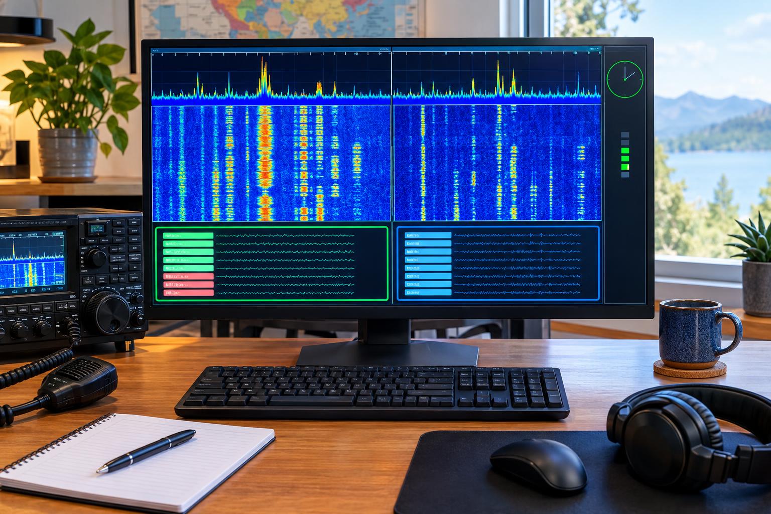
The LQ8 weak signal mode is timely because a September 2026 paper has placed it in front of technically curious operators, and current qFT8 documentation indicates practical software support for experimenting with it. For most HF operators, the right first question is not “Should I call CQ?” It is “Can I hear it, decode it, time it, and compare it fairly against FT8 and FT4 at my own station?”

That receive-first approach protects other operators from unnecessary QRM, helps you avoid chasing a mode that is inactive on your bands, and gives you a repeatable way to decide whether LQ8 deserves transmit testing. WSJT-X 3.0.2 is a logical baseline for FT8 and FT4 because WSJT-X is widely used for those modes, while qFT8 is the practical place to study LQ8 support and operating details. The goal is not to crown a universal winner. The goal is to produce station-specific evidence: decode threshold, time discipline, operator workload, and real on-air activity.

What You Can Compare Without Transmitting

A useful receive-only comparison does not require a perfect laboratory. It does require consistent conditions. You are comparing three things: the software’s ability to decode weak signals, your station’s timing and audio chain, and actual activity on the bands you operate.

  • FT8: the familiar 15-second weak-signal workhorse for structured QSOs on HF and VHF.
  • FT4: a faster mode used especially where quick exchanges matter, with a different tradeoff between speed and sensitivity.
  • LQ8: a newer mode to evaluate from documentation, current software support, and your own receive observations before transmitting.

Do not assume that a paper result or a software claim will translate directly to your antenna, receiver, noise floor, computer clock, and band conditions. HF noise, AGC behavior, sound-device levels, and local RFI can dominate the result.

Sources to Read Before You Start

Before running a lab, read the primary material rather than relying on band gossip. Start with the September 2026 paper at arXiv:2609.06427. Then review the current qFT8 project information at qFT8.com and the qFT8 manual. Use WSJT-X as your FT8/FT4 reference implementation and confirm that you are using the intended version, such as WSJT-X 3.0.2, for your comparison.

Software behavior changes over time, so avoid writing down old menu paths as if they are permanent. Record the exact versions used, operating system, radio model, interface method, and settings that affect decoding.

Station Setup for a Fair Receive-Only Comparison

Hardware and signal path

Use the same antenna, feed line, receiver, sound interface, sample rate, and RF gain strategy for each mode. If you compare LQ8 on one antenna and FT8 on another, your result is no longer a mode comparison. It becomes an antenna, band, and noise comparison.

  • Disable speech processing and transmit audio features; you are receiving only.
  • Set receiver bandwidth wide enough to include the digital passband you are observing.
  • Avoid heavy noise reduction, notch filtering, or aggressive DSP unless you use the same settings for all runs.
  • Keep waterfall gain and audio levels in the normal decoding range. Overdriven audio can look impressive and decode poorly.
  • Synchronize the computer clock with a reliable time source before each session.

For HF digital modes, time accuracy matters. A clock that is off by a second or two can make a good signal look bad. A receive-first lab should include a timing check before you blame a mode.

Recordings make the comparison repeatable

The cleanest amateur approach is to record audio or IQ from the same receiving session and replay it consistently. If the software allows decoding from saved files, use that. If not, you can still document live receive windows carefully. Saved recordings let you compare software settings without depending on changing propagation.

Label recordings with UTC date, band, frequency or dial setting, antenna, receiver bandwidth, software version, and whether the passband contained obvious interference. Do not publish other operators’ personal information beyond ordinary amateur call sign context, and be mindful of local rules and privacy expectations.

Measuring Decode Thresholds Without Inventing Numbers

A decode threshold is the approximate signal-to-noise condition where a mode stops decoding reliably. You do not need a calibrated RF laboratory to learn something useful, but you do need to avoid fake precision. If you cannot calibrate the whole chain, call the result “station-relative” rather than absolute.

Method 1: Relative audio attenuation

Start with a recording that decodes clearly in the target mode. Replay the same file while reducing audio level in known steps using audio software or a controlled playback chain. At each step, note whether the decoder produces the same messages, partial decodes, or no decodes.

  • Use the same recording segment for each run.
  • Change only one variable at a time.
  • Repeat a step if results vary from run to run.
  • Record the lowest attenuation step that still decodes consistently.

This does not give a formal published sensitivity number, but it can show whether LQ8, FT8, or FT4 is more tolerant in your station’s receive path under the same conditions.

Method 2: Live SNR distribution

During a busy band opening, collect decode reports from FT8 or FT4 over a fixed period, then collect LQ8 observations during a comparable period on the appropriate activity area if one is documented and legal for your privileges. Compare distributions, not one lucky decode. Write down the weakest repeated decodes, the number of unique stations heard, and how often decodes fail during QRM or fading.

The limitation is obvious: live HF conditions change. A 20-meter FT8 session at local afternoon and an LQ8 session after sunset are not equivalent. Treat live data as operating evidence, not laboratory proof.

Timing: The Hidden Variable in Weak-Signal Modes

Weak-signal modes rely on synchronized transmit and receive intervals. FT8 and FT4 operators already know that poor time sync causes missed decodes and awkward QSOs. When evaluating LQ8, timing deserves the same attention.

Build a timing checklist

  • Synchronize the computer clock before the session.
  • Confirm the radio is not adding unexpected receive latency through virtual audio routing.
  • Check whether the software shows receive offset, DT, or similar timing indicators.
  • Compare decode timing between software packages using the same saved recording when possible.
  • Do not transmit until you understand the cycle timing and message structure for the mode.

If your FT8 decodes show large time offsets from many stations, investigate your own clock first. If only one station shows a large offset, that may be the other station. If every mode struggles, look for computer sleep settings, overloaded CPU, unstable virtual audio cable settings, or an unsynchronized clock service.

Measuring Real On-Air Activity

A mode can be technically excellent and still be quiet. Before calling CQ in LQ8, find out whether anyone is listening where you operate. Your receive-first log should answer four questions:

  • Which bands show actual LQ8 activity from your location?
  • At what UTC times do decodes appear?
  • Are the decoded stations local, regional, or DX?
  • Is the activity recurring or just a one-time experiment?

For FT8 and FT4, you will usually have enough activity to benchmark your station quickly. For LQ8, you may need multiple sessions across several days and bands. Do not assume silence means the mode fails. It may mean your timing, frequency choice, software setup, or monitoring window is wrong—or simply that no one was transmitting at that time.

A Practical Logging Template

Use a simple spreadsheet or station notebook. The key is consistency.
  • UTC date/time: Use UTC, not local time.
  • Band and dial frequency: Include enough detail to reproduce the session.
  • Mode: FT8, FT4, or LQ8.
  • Software/version: For example, WSJT-X 3.0.2 for FT8/FT4 and the qFT8 version used for LQ8.
  • Antenna and receiver settings: Include bandwidth, preamp, attenuator, AGC, and DSP choices.
  • Clock status: Note whether time sync was freshly checked.
  • Decodes: Count unique call signs, weakest repeated decodes, and periods of no decode.
  • Interference notes: Local RFI, contest congestion, splatter, or storm noise.

This template helps prevent the classic mistake of comparing a clean FT8 opening with a noisy LQ8 session and calling it a technical conclusion.

Decision Matrix: When to Move From Receive to Transmit

Consider transmitting only after the receive evidence is strong enough to make an orderly QSO likely. A practical go/no-go matrix might look like this:

  • Go: You have confirmed software setup, time sync, receive decodes, message sequence, band legality, and an appropriate operating area.
  • Wait: You can run the software but have not decoded any real LQ8 signals yet.
  • Fix first: FT8/FT4 also decode poorly, suggesting a station, audio, timing, or RFI problem.
  • Do not transmit: You are unsure of your license privileges, band allocation, emission compatibility, or local rules.

When you do transmit, start conservatively. Use the minimum power needed for the communication objective, keep ALC and audio drive under control, and monitor the waterfall for conflicts. Digital modes are not exempt from courtesy or spectral responsibility.

Safety and Regulatory Caveats

Always operate within your license privileges and the allocations that apply in your jurisdiction. In the United States, amateur operators must also consider RF exposure requirements, station identification, good engineering practice, and avoidance of harmful interference. Band plans are voluntary in many contexts but still important for orderly operation. Technical capability does not automatically mean legal or courteous operation.

Digital-mode experimentation can encourage long automated receive sessions. Make sure your station is electrically safe, ventilated, and protected against weather and lightning risks. If you are using outdoor antennas, disconnect during storms and follow safe installation practices. Receive-only operation is lower risk than transmitting, but the station environment still matters.

Common Problems and Fixes

No decodes in any mode

Check the clock, audio input device, receiver mode, bandwidth, RF gain, and whether the waterfall actually shows signals. If FT8 on a busy band produces no decodes, solve that before judging LQ8.

Waterfall looks strong but decodes are poor

Reduce audio level, disable excessive DSP, and check for clipping. Strong visual traces are not the same as clean demodulation.

LQ8 shows no activity

Confirm you are using current qFT8 documentation, the correct mode selection, and an appropriate monitoring window. Try multiple bands and times. A new mode may have sparse activity compared with FT8.

FT8 decodes but LQ8 does not

That may indicate low activity, wrong setup, unsupported assumptions, or an actual performance difference at your station. Use recordings and notes before drawing conclusions.

FAQ

Is LQ8 a replacement for FT8?

Not necessarily. Treat it as a mode to evaluate. FT8 and FT4 have large user bases and established operating habits. LQ8 may offer interesting weak-signal behavior, but practical usefulness depends on software maturity, activity, timing, and operator adoption.

Can I compare modes from signal reports alone?

Signal reports are useful but incomplete. Different stations, antennas, paths, and software settings can distort the comparison. A better approach combines recordings, controlled replay when possible, live observation, and careful station notes.

Should I call CQ if I have never decoded LQ8?

It is better to wait. Decode real signals first, confirm your timing and setup, understand the message sequence, and verify that transmitting is legal and appropriate on the band.

Why use WSJT-X 3.0.2 as the baseline?

Using a known FT8/FT4 implementation gives you a practical reference point. If your station cannot decode normal FT8/FT4 activity reliably in WSJT-X, your LQ8 experiment may be compromised by station setup rather than mode performance.

Key Takeaways

  • The best first step with the LQ8 weak signal mode is receive-only observation, not immediate CQ.
  • Use WSJT-X 3.0.2 as a practical FT8/FT4 baseline and qFT8 documentation for LQ8 setup.
  • Measure station-relative decode thresholds with controlled recordings or carefully logged live sessions.
  • Time synchronization, audio levels, receiver bandwidth, and local RFI can dominate weak-signal results.
  • Move to transmitting only after confirming activity, legality, timing, message flow, and courteous spectrum use.
Posted on — Leave a comment

Beyond the ISS on 145.825: Find Active APRS Digipeater Satellites and Verify Packets Before You Transmit

Why 145.825 MHz Is Bigger Than “Just the ISS”

For many operators, the first packet satellite target is the International Space Station digipeater on 145.825 MHz. That is a good starting point, but it can also create a bad habit: assuming that every APRS satellite opportunity is the ISS, always active, and always ready for another beacon. A better approach is to treat APRS satellite digipeater 145.825 operation as a receive-first, status-checked, pass-specific activity.

APRS via satellite is usually 1200-baud AX.25 packet sent as FM audio, commonly heard around 145.825 MHz for several amateur spacecraft and ISS-related activity. The exact operating status, packet path, and supported mode can change. Some spacecraft are fully operational, some are experimental, and some are listed as future or testing missions. AMSAT’s October 31, 2026 satellite information is notable because upcoming and testing APRS-capable spacecraft such as Lilium-4 and PARUS-6U1 appear alongside live status resources. That does not mean every listed satellite is available for routine use today. It means operators should learn how to separate “planned,” “testing,” “heard,” and “active digipeater” before transmitting.

Start With Status, Not With the PTT Button

The most useful question is not “What frequency do I transmit on?” It is “Is there an active digipeater, during this pass, using a path I can confirm?” Begin with the AMSAT live digipeater satellites page and the broader AMSAT satellite status page. These resources help you see whether operators are reporting successful access, telemetry, digipeating, or silence.

Use the AMSAT upcoming satellites page differently. It is useful for awareness: new spacecraft, planned capabilities, frequencies, and experimental missions. It is not the same as a green light to transmit. A satellite can be launched but not commissioned, capable of APRS but not enabled, or in a testing phase where routine amateur access is discouraged.

A Practical Status Workflow

  • Check the live digipeater list: Look for spacecraft currently reported as supporting packet or APRS digipeating.
  • Check recent user reports: A satellite may be technically operational but not recently heard from your region.
  • Confirm the uplink, downlink, and path: Do not assume that 145.825 MHz and ARISS apply to every satellite.
  • Download current Keplerian elements: Use fresh Keps so your pass prediction is close enough for a short VHF pass.
  • Receive first: Decode actual packets before sending your own.

Understanding Keps and Passes Without Overcomplicating It

Keplerian elements, often shortened to Keps, describe a satellite’s orbit so your tracking software can predict passes. For APRS satellite work, Keps matter because useful passes are brief. A low-Earth-orbit satellite may be above your local horizon for only several minutes, with the strongest signals near closest approach and weaker copy near acquisition of signal and loss of signal.

For a first attempt, choose a pass with a maximum elevation of at least 30 degrees if possible. Higher passes reduce path loss, shorten the distance through obstacles, and give a handheld antenna or modest vertical a better chance. Low passes can work, but they are less forgiving and more likely to produce partial decodes.

Keep your station clock accurate. APRS packets are short, but pass timing is everything. If your computer, phone, or radio clock is off by a few minutes, you may aim, listen, or transmit at the wrong time. Internet time synchronization before going portable is a simple fix.

Packet Paths: The Detail That Makes or Breaks a Contact

In terrestrial APRS, operators often see paths such as WIDE1-1 or WIDE2-1. Satellite APRS is different. Using terrestrial wide-area paths through a satellite is poor practice and may not work at all. Satellite digipeaters commonly require a specific alias such as ARISS or another published path for that spacecraft. Always use the current published path from a trusted satellite status or operations source.

A typical APRS satellite packet might be addressed to an APRS destination such as CQ, APRS, or a software-generated destination, with a digipeater path set to the satellite’s required alias. For ISS APRS, ARISS has long been a common path. That fact should not be generalized to every spacecraft. Newer or experimental satellites may use a different alias or may not support routine digipeating even if they carry APRS-capable hardware.

Good Path Discipline

  • Use only the path specified for that satellite.
  • Avoid terrestrial WIDE paths on satellite passes.
  • Keep messages short. A short position or brief CQ-style packet is easier to decode and less likely to crowd the pass.
  • Do not beacon continuously. One or two well-timed packets during a pass is usually more considerate than repeated transmissions.

Receive-First Packet Decoding: Your Best Operating Filter

Receive-first operation means you verify that the satellite is actually being heard and decoded at your station before you transmit. This protects the pass for everyone and prevents blind transmissions into a dead, disabled, or misconfigured link.

A simple receive chain can be a 2-meter FM receiver feeding packet audio to a computer, tablet, or TNC. Common software TNCs can decode 1200-baud AFSK AX.25 from discriminator or speaker audio, depending on your interface and levels. The key is clean audio: not too low, not distorted, and not aggressively filtered by audio processing. If your receiver has selectable bandwidth, normal FM settings that preserve packet tones are usually more useful than voice-enhancement features.

What to Look For Before Transmitting

  • Decoded packets with recognizable call signs: This confirms you are receiving real AX.25 traffic, not just noise.
  • The expected satellite path or digipeater alias: This helps confirm you are hearing the correct spacecraft activity.
  • Reasonable timing: Packets should appear during the predicted pass, not randomly at unrelated times.
  • Your own local RF environment: If you hear strong terrestrial APRS overload, intermod, or desense, fix that before attempting the satellite.

If you cannot decode anything on a strong, high pass when other operators are reporting success, troubleshoot receive before transmitting. Check frequency, squelch, audio level, antenna polarization, pass time, and Doppler tuning.

Doppler, Frequency, and Antenna Choices on 145.825

At VHF, Doppler shift is smaller than on UHF but still real. On 145.825 MHz, the shift across a low-Earth-orbit pass can be a few kilohertz. Many 1200-baud FM packet setups tolerate some error, especially with wider FM receiver bandwidth, but tuning closer helps. Some operators leave the radio on 145.825 MHz for the entire pass; others step slightly high early in the pass and slightly low late in the pass. Your radio’s tuning step and receiver bandwidth will influence the best approach.

A handheld directional antenna, such as a small 2-meter Yagi or satellite-style dual-band antenna, can make a large difference. A quarter-wave vertical may decode strong passes, particularly if it has a clear view of the sky, but it is less controllable and may suffer from poor signal angles. Indoors, metalized insulation, low-E glass, appliances, and house wiring can attenuate or distort signals. If you are struggling, move outside with a clear horizon and keep feed-line loss low.

Transmit Etiquette on a Shared Short Pass

Satellite APRS passes are shared channels. Everyone in the footprint may be trying to use the same digipeater during the same few minutes. Unlike a local terrestrial digipeater, the satellite hears a large geographic area at once. Stronger stations can capture the receiver, and repeated beacons can prevent weaker stations from getting through.

Use the minimum practical power for your station and conditions. Five watts into a handheld directional antenna is often technically capable on favorable passes, but capability is not permission to monopolize the channel. Time your packet when the satellite is above clutter and when you are likely to be heard, not every few seconds. If the pass is crowded, receive only and learn from the traffic.

Regulatory and Safety Caveats

In the United States, amateur digital transmissions must comply with FCC Part 97 rules, including identification, permitted content, third-party traffic restrictions, and the prohibition on obscured meaning for ordinary amateur communications. The ARRL’s overview of digital transmissions is a useful starting point, but operators should consult current FCC rules and applicable international regulations when operating outside the United States or communicating through satellites with global footprints.

Also consider RF safety. Even modest VHF power can exceed recommended exposure limits at close range, especially with directional antennas. Keep antennas away from faces and bystanders while transmitting. For portable work, watch for trip hazards, overhead lines, unstable masts, weather, and battery safety. Do not aim antennas where you cannot maintain physical control of the station.

Example: A Conservative First APRS Satellite Session

Suppose you want to try an APRS satellite digipeater on 145.825 MHz this weekend. The careful plan looks like this:

  • Two days before: Check AMSAT live digipeater and status pages. Identify one candidate satellite that is actively reported, not merely planned.
  • One day before: Update Keps in your tracking app. Pick one high pass and one backup pass.
  • Before the pass: Set your receiver to 145.825 MHz, configure 1200-baud packet decoding, open squelch or set it low enough not to clip packets, and verify audio levels.
  • During the first pass: Receive only. Confirm actual decoded packets and note the path being used.
  • During a later pass: If the satellite is active and your setup decodes reliably, transmit one short packet using the published path. Then listen for your digipeated packet rather than immediately transmitting again.

This method is slower than blindly beaconing, but it teaches you more and reduces unnecessary interference.

Common Problems and Fixes

No Packets Decoded

Confirm the pass time, Keps, frequency, antenna connection, and audio routing. Open the squelch or reduce squelch so the first part of a packet is not clipped. Try a higher-elevation pass before changing every setting at once.

Packets Heard but Not Decoded

Audio may be distorted, too loud, too quiet, or filtered. Disable noise reduction and voice processing. Adjust input levels so the software TNC sees clean audio without clipping.

You Decode Others but Not Yourself

Check the digipeater path, deviation, transmit audio level, and timing. If your packet is too frequent, too long, or sent at low elevation through obstructions, it may not be captured. Reduce message length and try once near the strongest part of the pass.

Status Pages Disagree

That is normal with time-sensitive spacecraft operations. Prefer recent confirmed reports and official or well-maintained status pages. If in doubt, receive only.

FAQs

Is every APRS satellite on 145.825 MHz?

No. 145.825 MHz is common and important, especially for ISS-related APRS activity, but satellites can use different uplinks, downlinks, modes, and aliases. Always verify current information.

Can I use my normal terrestrial APRS beacon settings?

Not without checking them. Terrestrial paths such as WIDE1-1 or WIDE2-1 are not appropriate for satellite use. Use the satellite’s published path and keep packets short.

Do I need full-duplex operation?

Full duplex is helpful because you can hear whether your packet was digipeated while transmitting or immediately after. It is not always mandatory for learning, but receive-first decoding is strongly recommended.

Are upcoming satellites fair game once they appear on a list?

No. Upcoming or testing listings indicate capability or plans, not routine access. Wait for commissioning information, status reports, and confirmed operating guidance.

Key Takeaways

  • Do not assume the ISS is the only APRS opportunity on 145.825 MHz.
  • Use AMSAT live and status pages to confirm active digipeater operation.
  • Treat upcoming satellites such as Lilium-4 and PARUS-6U1 as watch-list items until routine access is confirmed.
  • Update Keps, choose favorable passes, and decode packets before transmitting.
  • Use the correct satellite path, avoid terrestrial WIDE paths, and transmit sparingly.
  • Follow current regulations, identification rules, and RF safety practices.

The best APRS satellite operators are patient listeners first. If you can confirm the satellite, decode the downlink, use the right path, and transmit briefly, you will be a better neighbor on a very small shared channel.

Posted on — Leave a comment

ARRL Digital Contest Without Bad QSOs: Grid Exchanges, Attended Operation, and Online-Only Log Submission

Why “Bad QSOs” Happen in a Digital Contest

The ARRL Digital Contest rewards careful station setup as much as fast clicking. FT4, FT8, and other narrow digital modes make it easy to complete many contacts quickly, but they also make it easy to log the wrong grid, accept a broken exchange, mis-handle a duplicate, or submit a log that does not match the official requirements.

The most important preparation is not a bigger antenna or more power. It is building a contest workflow that follows the current ARRL Digital Contest rules, records the required exchange correctly, and produces a clean Cabrillo log for online submission. ARRL’s published information for this event emphasizes several points operators should treat as nonnegotiable: the exchange is a 4-character Maidenhead grid square, operation must be attended, and ARRL has noted that contest entries are online-only beginning September 30, 2026. Always verify the live rule page before operating, because contest rules can change.

Start With the Current Rules, Not Old Memory

Before configuring software, open the official contest page and calendar. Use the current rule document for the contest year you will operate, not a saved copy from a previous season. The ARRL Digital Contest is not simply “any FT8 weekend.” It has its own eligible modes, band rules, categories, exchange requirements, and log submission procedure.

When checking the rules, confirm the contest dates and times, eligible bands, permitted digital modes, entry category, power category, exchange, scoring method, and log deadline. Also confirm whether any special rule notes apply to remote operation, assistance, or software automation. Digital contesting changes quickly, and software defaults do not always match contest rules.

The Exchange: Send the Right 4-Character Grid

The key exchange item is your 4-character Maidenhead grid square, such as FN31, EM12, DM79, or CN87. A 4-character grid identifies a geographic area using two letters and two numbers. Many logging and weak-signal programs also support 6-character grids, but the contest exchange is the 4-character form unless the current rules state otherwise.

If your station location is fixed, enter the correct 4-character grid in every program involved in the contact chain: digital-mode software, contest logger, rig-control utility if applicable, and any log-conversion tool. If you operate portable, rover-style, from a temporary QTH, or through a remote station, verify which location the rules require you to use and set the grid accordingly before making contacts.

Common Grid Exchange Mistakes

  • Using a home grid while operating portable: If the transmitter is somewhere else, your usual home-grid macro may be wrong.
  • Sending six characters when four are expected: Some software may display your full locator. Make sure the transmitted contest exchange matches the rule requirement.
  • Logging the other station’s old grid: Imported callbook or previous-contact data can conflict with the grid actually exchanged on the air.
  • Typing letter-number lookalikes: Grids such as EN50 and EM50 differ by one letter but represent different areas.
  • Changing grids mid-contest without tracking it: Portable operators must make sure the log reflects the correct exchange for each contact.

A good pre-contest habit is to transmit a practice message into a dummy load or monitor-only setup where appropriate, or use the software’s message preview, to confirm exactly what your station will send. Do not discover during the contest that your macro says “RR73” but never sends your grid.

Build an FT4/FT8-Style Contest Setup That Logs Cleanly

A reliable digital contest station has four layers working together: the radio, the audio interface, the digital-mode program, and the logger. A failure in any layer can create bad contacts or bad log data.

Radio and Interface Checks

  • Confirm CAT control or manual band tracking so the log records the correct band.
  • Set transmit audio drive conservatively to avoid overdriving the transmitter or creating unnecessary splatter.
  • Use a clean, stable audio path and avoid unintended computer sound effects entering the transmit stream.
  • Verify PTT control before the contest.
  • Confirm your antenna system, feed line, and SWR are suitable for the bands you intend to use.

Computer and Clock Checks

FT4 and FT8 depend on accurate time synchronization. Before the contest, make sure your computer clock is being synchronized by a reliable time source. If your clock is off, other stations may not decode you reliably, and you may miss replies even though your transmitter and antenna are working.

  • Disable sleep settings that could interrupt logging or time sync.
  • Keep a backup copy of the log file during longer operating sessions.
  • Record your exact software versions in your personal notes in case troubleshooting is needed later.
  • Avoid making major software upgrades immediately before the contest unless necessary.

Attended Operation: Stay in Control of Every QSO

The ARRL Digital Contest rules emphasize attended operation. In practical terms, do not set up a station to call, answer, complete, or log contacts while you are away from the operating position. Digital software can automate parts of message sequencing, but contest compliance depends on the operator remaining present, responsible, and in control.

Attended operation matters because the operator must make judgment calls: whether the decoded call sign is correct, whether the exchange was actually received, whether a duplicate should be logged, whether the radio is still on an authorized frequency, and whether the station is transmitting a clean signal. A fully unattended digital station can generate questionable contacts quickly.

A Practical Attended-Operation Standard

  • Be at the operating position and monitoring the software and radio behavior.
  • Initiate or approve contacts as required by the rules and your entry category.
  • Watch for wrong-grid, wrong-call, or partial-decode situations.
  • Stop transmitting if the station behaves unexpectedly.
  • Remain responsible for band privileges, RF exposure compliance, and station identification.

If you operate remotely, the same principle applies: the licensed control operator must remain actively in control, and the station must comply with applicable FCC rules, contest rules, and local station requirements. Technical capability does not automatically mean contest eligibility.

What Counts as a Contact You Should Log?

For a contest log, a QSO should represent a completed two-way exchange as required by the rules. Do not log a contact merely because you decoded a station, called it, or saw a partial message. You need enough information to support the required exchange and the correct station identity.

A cautious workflow for FT4/FT8-style operation is simple: decode the other station’s call, exchange the required contest information, confirm completion according to the mode’s message sequence and contest practice, then allow the logger to record the QSO. If something looks wrong, fix it before moving on.

Examples of QSOs to Review Before Logging

  • Partial call sign: You decoded “K1ABC” once, but the following message looked like “K1ABD.” Resolve the call before logging.
  • Missing grid: The contact completed with signal reports only, but the contest requires a grid. Do not assume a grid from a database.
  • Band mismatch: The radio is on 20 meters, but the logger shows 15 meters because CAT control failed.
  • Duplicate contact: The other station calls again on the same band. Check the current rules and your logger’s duplicate handling before deciding whether to log it.
  • Wrong station answered: In crowded digital windows, another station may respond while your software still highlights the first one.

Logging: Make the Cabrillo File Match the Contest

Most contest submissions require a Cabrillo-formatted log generated by logging software or a contest-capable digital program. The exact header fields and QSO line format depend on the event. Do not hand-edit a Cabrillo file unless you understand the format, because a small mistake can create a rejected or misclassified entry.

Before exporting, check these items carefully:

  • Your call sign is correct and consistently formatted.
  • Your entry category, power, operator status, and station information match your actual operation.
  • Each QSO has the correct date and UTC time.
  • Each QSO has the correct band or frequency.
  • The sent exchange is your correct 4-character grid.
  • The received exchange is the other station’s actual received grid, not imported profile data.
  • The mode field is appropriate for the contact and accepted by the contest log format.

Save the original application log and the exported Cabrillo file. If your logger supports a log-check report, run it. Look for blank exchanges, impossible bands, duplicate records, time-order problems, and mismatched call signs. A clean log is not just about score; it is about accurately representing what happened on the air.

Online-Only Submission Planning

ARRL has noted that online-only contest submissions begin September 30, 2026. For the ARRL Digital Contest, plan your workflow around the online submission process rather than paper forms or informal email habits. The safest approach is to export the Cabrillo file immediately after the contest, review it, and submit it through the official ARRL contest submission system within the published deadline.

Online submission does not remove the need to inspect the file. The upload page may catch some errors, but it cannot know whether you sent the wrong grid, operated from the wrong category, or logged a contact that was not completed. Treat the upload confirmation as the final step, not the only step.

Post-Contest Log Checklist

  • Export the log in the required format.
  • Open the file in a plain-text editor and scan the header.
  • Verify call sign, category, grid, power, and operator information.
  • Confirm QSO times are in UTC.
  • Check for blank or suspicious exchanges.
  • Submit through the official online system.
  • Save the confirmation or receipt for your records.

Safety and Regulatory Caveats

Digital modes can create long transmit periods at high duty cycle compared with casual SSB operation. Make sure your transmitter, amplifier, tuner, feed line, and antenna are rated for the duty cycle and power level you intend to use. Reduce power if equipment becomes hot, unstable, or distorted.

US operators must follow FCC rules, license-class privileges, band limits, station identification requirements, and RF exposure obligations. International operators should follow their own regulator’s rules. Contest rules do not override legal requirements. Also consider ordinary station safety: proper grounding and bonding, lightning precautions, safe antenna supports, and careful cable routing to prevent trips or equipment damage.

Key Takeaways

  • The ARRL Digital Contest exchange centers on the correct 4-character Maidenhead grid.
  • Do not rely on old settings, old PDFs, or software defaults without checking the current rules.
  • Attended operation means the operator remains present, responsible, and in control.
  • Bad QSOs often come from wrong grids, partial decodes, time-sync problems, CAT failures, and careless log exports.
  • ARRL has noted online-only submissions beginning September 30, 2026, so build an online Cabrillo submission workflow now.

FAQ

Can I use FT8 or FT4 in the ARRL Digital Contest?

FT8 and FT4 are common digital contest modes, but always verify the current ARRL Digital Contest rules for the eligible mode list and any exclusions. Do not assume that every digital mode or every band is automatically valid.

Should I send a 6-character grid if my software knows it?

For this contest, the rules emphasize a 4-character grid exchange. Configure your contest messages and logger around the required 4-character format unless the current official rules specify otherwise.

Is automatic sequencing the same as unattended operation?

No. Software may assist with message sequencing, but unattended contest operation is a separate issue. The operator should remain at the operating position, monitor contacts, and stay in control of the station.

What is the best way to avoid log rejection?

Use the current official rules, configure the correct contest exchange, keep your clock synchronized, verify CAT and band logging, export Cabrillo correctly, and submit through the official online system before the deadline.

Posted on — Leave a comment

Turn WSPR Spots Into a Personal Propagation Tool: Build a HamSCI-Style Space Weather Station at Home

Why Build a HamSCI-Style Station Around WSPR?

A HamSCI Personal Space Weather Station is best understood as a disciplined amateur-radio receiving and measurement station, not just another digital-mode setup. Instead of asking only, “Can I make the contact?” the station asks, “What is the ionosphere doing, and how can I use that information tomorrow?”

HamSCI’s Personal Space Weather Station work encourages distributed, repeatable measurements by radio amateurs and citizen scientists. The 2026 HamSCI program materials highlight PSWS deployments, WSPR sensing, and an expanded role for volunteer-host stations. That makes this a good time for technically curious operators to turn ordinary WSPR spots, FST4W decodes, and HF Doppler observations into a personal propagation tool.

The goal is not to replace professional space-weather instruments. It is to build a useful home system that helps you recognize band openings, compare antennas, notice disturbances, and contribute cleaner observations when you choose to share data.

What WSPR Spots Can—and Cannot—Tell You

WSPR, the Weak Signal Propagation Reporter mode, is a low-power digital beaconing system used on amateur bands. A typical WSPR transmission carries a call sign, Maidenhead grid, and power level. Receiving stations decode the signal and often upload spots to public databases. For propagation study, each spot is a small data point: frequency, time, path, signal-to-noise ratio, drift, transmitter location, receiver location, and reported power.

That is valuable, but it is not a perfect map of the ionosphere. WSPR data is shaped by who happens to be transmitting, where receivers are located, what antennas they use, receiver noise, local interference, software settings, and whether stations upload spots. A missing spot does not prove that a path was closed. It may only mean nobody transmitted, nobody listened, or the local noise floor was too high.

The trick is to treat WSPR as a long-term sensing network. Single spots are interesting. Patterns are useful. Multi-day comparisons by band, time of day, path length, and direction can become a practical operating aid.

Core Station Architecture

A home station inspired by HamSCI PSWS principles can be built in layers. Start simple and add measurement quality as your interest grows.

Layer 1: Receive-Only WSPR and FST4W Monitoring

The simplest useful station is a stable HF receiver, a modest antenna, a computer, and decoding software. An SDR receiver is convenient because it can cover multiple bands, record spectrum, and feed digital-mode software. A conventional transceiver with audio output also works.

  • Receiver: HF SDR or transceiver with reasonably stable frequency control.
  • Antenna: End-fed wire, dipole, loop, vertical, or active receive antenna suited to your space and noise environment.
  • Computer: Low-power desktop, laptop, or single-board computer with reliable timekeeping.
  • Software: WSJT-X for WSPR and FST4W decoding, plus logging or database tools for analysis.
  • Time source: Internet time synchronization at minimum; GNSS timing if you later pursue tighter measurements.

FST4W, available in the WSJT-X family of weak-signal modes, is designed for beacon-style propagation work and can be useful where very weak signals and longer transmit/receive cycles are acceptable. As with WSPR, the value increases when your time, frequency, station description, and logging practices are consistent.

Layer 2: Controlled Local Beaconing

If your license privileges, band plan, station design, and local regulations allow it, you can add low-power WSPR or FST4W transmissions. Keep power levels modest, identify properly, follow current band allocations, and avoid creating interference. In the United States, amateur operators must comply with FCC rules, including operating privileges and RF exposure evaluation requirements. Other countries have different rules.

A controlled beacon is especially useful when you want to compare how your signal is heard on different bands across the day. However, transmitting is optional. A receive-only station can still teach you a great deal.
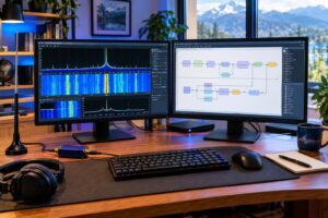
Layer 3: HF Doppler Monitoring

HF Doppler monitoring looks for tiny frequency shifts in stable signals after they reflect or refract through the ionosphere. These shifts can be associated with changing ionospheric conditions, traveling ionospheric disturbances, sunrise and sunset transitions, geomagnetic activity, and other effects. HamSCI PSWS-related work has emphasized repeatable observations of signals such as standard-frequency transmissions and other stable sources where appropriate.

For useful Doppler work, receiver stability matters more than raw sensitivity. A receiver locked to a GPS-disciplined oscillator or another stable reference is far better than a free-running receiver for small shift measurements. You do not need to start there, but it is the direction to aim if Doppler analysis becomes serious.

A Practical Starter Build

Here is a realistic first version for a US amateur operator who wants useful data without building a laboratory-grade system on day one.

  • Antenna: 40–80 ft wire outdoors if possible, with appropriate matching and common-mode choking; or a small receive loop if local noise is severe.
  • Receiver: HF-capable SDR with adequate dynamic range for your RF environment.
  • Computer: Always-on mini PC or laptop with stable networking and automatic time synchronization.
  • Software: WSJT-X for WSPR/FST4W, optional SDR spectrum software, and a spreadsheet or database for summaries.
  • Logging fields: UTC time, band, mode, decoded call, grid, SNR, drift, frequency, antenna, receiver, noise notes, and any station changes.
  • Data routine: Review daily plots by UTC hour and band; review weekly path maps and SNR trends.

This setup is enough to answer questions such as: When does 20 meters open from my location? Does 30 meters stay useful after local sunset? Is my receive noise worse on weekdays? Does my new antenna increase spot counts broadly, or only in one direction?

Turning Spots Into Decisions

The practical value comes from converting decodes into operating decisions. Do not chase every individual spot. Instead, build simple comparisons.

Band-by-Hour Matrix

For each band, count unique stations heard per UTC hour. After two or three weeks, patterns emerge. You may find that 17 meters opens briefly around local morning, 20 meters carries midday paths, and 40 meters becomes dependable after sunset. This matrix becomes your personal band-opening calendar.

Path Direction Review

Group spots by general direction from your grid: northeast, southeast, southwest, northwest, and long-path possibilities. A wire antenna may favor certain headings. A loop may null local noise but reduce some desired paths. When the same band repeatedly favors one direction at a certain hour, you have actionable information for DXing, POTA hunting, or scheduled QSOs.

SNR Trend Instead of Spot Count Alone

Spot counts are affected by activity. Signal-to-noise trends add another dimension. If several distant transmitters show stronger SNR at similar times on the same band, the band may genuinely be improving. If spot counts fall but your noise floor also rises, the problem may be local interference rather than propagation.

Adding HF Doppler as a Second Sensor

WSPR and FST4W tell you whether weak signals were decoded. HF Doppler monitoring can show that the propagation medium itself is moving or changing. This is where your station begins to look more like a personal space-weather instrument.

A beginner-friendly approach is to dedicate one SDR channel or receiver profile to a stable HF signal and watch frequency offset over time. Use the most stable frequency reference you can. Record UTC time, nominal frequency, measured offset, receiver configuration, and notes about local equipment changes. Do not overinterpret every wiggle. Look for repeatable features around sunrise, sunset, solar events, geomagnetic disturbances, and regional comparisons if other stations are sharing similar observations.

When Doppler traces change at the same time your WSPR paths fade, shift band preference, or show abnormal SNR, you have a richer picture than spots alone can provide.

Noise Control: The Hidden Success Factor

Many home stations fail as propagation sensors because they are really measuring local noise. Before blaming the ionosphere, reduce preventable interference.

  • Run the receiver from a clean power supply or battery during tests.
  • Use ferrite chokes on USB, Ethernet, power, and feed-line paths.
  • Separate receive antennas from household electronics when possible.
  • Document when solar inverters, chargers, LED lighting, HVAC equipment, or computers are operating.
  • Compare day and night noise floors on quiet frequencies.

Good notes are as important as good hardware. If you change the antenna, add a preamp, move the feed line, update software, or relocate the receiver, mark the date. Otherwise, you may mistake a station change for a space-weather event.

Safety and Regulatory Caveats

Receive-only monitoring is usually straightforward, but antennas still create real safety issues. Keep wires clear of power lines. Use proper strain relief, weatherproofing, grounding and bonding practices appropriate to your installation, and lightning protection where outdoor antennas enter a building. Disconnect antennas during storms when appropriate, and follow electrical codes and local requirements.

If you transmit WSPR or FST4W, operate only within your license privileges and current band allocations. Use clean signals, appropriate duty cycles, and conservative power. In the US, review FCC amateur rules and RF exposure obligations. Technical capability does not automatically mean legal permission.

Example Workflow: From Raw Spots to a Propagation Note

Suppose your station in the central United States monitors 40, 30, 20, and 17 meters for several weeks. You notice that 20 meters usually produces strong morning and afternoon spots, but on one day the count drops sharply after 1700 UTC. At the same time, 30 meters remains active, 40 meters is normal after sunset, and your local noise notes show no equipment changes. Your Doppler trace also shows unusual movement near the same period.

You should not claim a specific cause from that alone. But you can write a useful station note: “On this date, 20-meter WSPR reception from this location declined after 1700 UTC compared with the prior week; 30 and 40 meters remained comparatively usable; no local station changes were recorded; HF Doppler monitoring showed concurrent variation.” That is honest, searchable, and useful for your future operating decisions.

How to Make Your Data More Useful

  • Use UTC everywhere. Local time creates confusion when comparing with other stations.
  • Keep station metadata current. Antenna type, height, receiver, frequency reference, and grid square matter.
  • Avoid constant tinkering. Stability makes trends easier to trust.
  • Separate experiments. Change one major variable at a time when comparing antennas or receivers.
  • Archive raw data. Summaries are helpful, but raw decodes allow better analysis later.
  • Label estimates clearly. Do not turn rough observations into precise claims.

Frequently Asked Questions

Do I need an expensive station to start?

No. A modest SDR, a usable antenna, stable time synchronization, and disciplined logging can produce useful personal propagation information. Higher-grade frequency references and receivers become more important when you pursue HF Doppler measurements or multi-band precision work.

Is WSPR better than FST4W?

They are different tools. WSPR has a large established user base and spot ecosystem. FST4W is useful for weak-signal beacon-style propagation experiments and offers options that may suit certain paths and time intervals. Many experimenters can benefit from understanding both.

Can I predict DX openings from my own spots?

You can improve your odds of choosing the right band and time, but you cannot guarantee a contact. Propagation is variable, and WSPR activity patterns are not the same as actual on-air activity for voice, CW, or other digital modes.

Should I upload spots?

Uploading can help the broader amateur and research community, but only if your station time, frequency, and metadata are reasonably accurate. If you are experimenting with unstable settings, keep local logs until the system is behaving consistently.

Key Takeaways

  • A HamSCI-style home station turns casual decodes into repeatable propagation observations.
  • WSPR provides broad, practical path data, but it must be interpreted with awareness of activity and station bias.
  • FST4W adds another weak-signal beaconing option for structured experiments.
  • HF Doppler monitoring can reveal ionospheric motion and change when paired with a stable receiver reference.
  • Station notes, UTC logging, noise control, and consistent configuration are what make the data valuable.

Legitimate Resources

A home propagation station does not have to be elaborate to be meaningful. Start with clean receive data, build repeatable habits, add timing and Doppler capability when ready, and let your own station history guide your operating choices. That is where WSPR spots become more than dots on a map—they become a personal view of the ionosphere over your own antennas.